Metal laser melting additive manufacturing method

A laser melting additive and manufacturing method technology, applied in the field of additive manufacturing, can solve problems such as easy to produce spheroidization and pores, difficult to completely change the continuous network distribution of thick-layer carbides, and difficult to transfer stress, so as to improve the forming quality Effect

Active Publication Date: 2015-03-11
CENT SOUTH UNIV
View PDF2 Cites 49 Cited by
  • Summary
  • Abstract
  • Description
  • Claims
  • Application Information

AI Technical Summary

Problems solved by technology

However, due to the extremely complicated solidification process of the laser molten pool, the above-mentioned crack prevention methods still have certain limitations: first, the above methods are difficult to completely eliminate micro-cracks, especially for highly crack-sensitive materials such as nickel-based and cobalt-based materials; secondly, the above methods are difficult universally applicable
[0004] Second, the brittle ceramic phase (such as M 7 C 3 ,M 23 C 6 ) are easily distributed around the matrix grains in a continuous network structure, which greatly reduces the strength and toughness of laser additive manufacturing
Although the presence of ceramic phases can greatly improve the hardness and wear resistance of laser additive manufacturing parts, these ceramic phases distributed in a network form isolate the metal grains from each other, greatly weakening the bonding force between the grains, resulting in laser The overall performance of additively manuf

Method used


Image

  • Metal laser melting additive manufacturing method
  • Metal laser melting additive manufacturing method

Examples


Embodiment 1

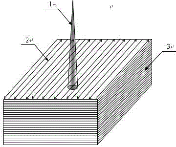
[0025] (1) For the forming of high-performance 316L stainless steel alloy parts, use 3D modeling software to design the 3D CAD model of the part, then process it with slicing software and save it as an STL file, and send the data information of the STL file to the laser additive manufacturing for rapid processing Forming equipment: use SLM to process the current slice layer, the powder feeding mechanism spreads a layer of 316L stainless steel powder with a thickness of about 0.05mm and a particle size of 10μm on the metal substrate, and the power of the fiber laser is 200W; figure 1 Among them, 1 is the laser beam; 2 is the path of the laser beam; 3 is the multi-layer entity.

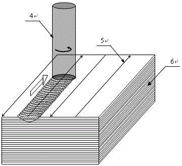
[0026] (2) After the current slice layer is processed by SLM, the cubic BN material is selected as the stirring head 4, and friction stir processing is performed on the laser melting area line by line. Among them, the diameter of the rotating shaft shoulder is 2mm, the rotating speed is 500rpm, the trav...

Embodiment 2

[0029] (1) For the forming of high-performance cobalt-based Co-27Cr-5Mo-0.5Ti alloy parts, use 3D modeling software to design the 3D CAD model of the part, and then process it with slicing software and save it as an STL file. The data of the STL file The information is sent to laser additive manufacturing rapid prototyping equipment; LENS is used to process the current slice layer, so that 500W YAG laser, 50g / min cobalt-based alloy powder, and Ar gas are simultaneously input to the substrate, and the layer thickness is 0.15mm;

[0030] (2) After the LENS finishes processing the current slice layer, the cubic BN material is selected as the stirring head 4, and the LENS area is subjected to row-by-row friction stir processing. Among them, the diameter of the rotating shaft shoulder is 2mm, the rotating speed is 500rpm, the traveling speed is 500mm / min, the FSP down pressure is 0.01mm, and the thickness of the FSP deformed layer is 0.3mm, so as to ensure that the thickness of the ...

Embodiment 3

[0033] (1) For the forming of high-performance Al-Si alloy parts, use 3D modeling software to design the 3D CAD model of the part, then process it with slicing software and save it as an STL file, and send the data information of the STL file to laser additive manufacturing Rapid prototyping equipment; SLM technology is used to process the current slice layer, the powder feeding mechanism spreads a layer of Al-Si alloy powder with a thickness of about 0.05mm and a particle size of 20μm on the metal substrate, and the fiber laser power is 150W;

[0034] (2) After the current slice layer is processed by SLM, the tool steel is selected as the stirring head 4 to perform friction stir processing on the laser melting area line by line. Among them, the diameter of the rotating shaft shoulder is 1mm, the rotating speed is 1000rpm, the traveling speed is 800mm / min, the FSP down pressure is 0.01mm, and the thickness of the FSP deformed layer is 0.2mm, so as to ensure that the thickness o...


PUM

PropertyMeasurementUnit
Thicknessaaaaaaaaaa
Particle sizeaaaaaaaaaa

Abstract

The invention discloses a metal laser melting additive manufacturing method. After each layer is machined by utilizing the laser additive manufacturing method, a single-layer laser photocoagulation area is modified by utilizing a selective friction stir welding, photocoagulation cracks are eliminated and nanocrystalline is formed. Each additive-manufactured layer is subjected to laser melting and friction stir welding and multiple layers are machined by the method repeatedly, so that nanocrystalline complex metal components with high strength and ductility and no cracks are manufactured. The laser melting additive manufacturing method provided by the invention comprises a selective laser melting technique based on powder bed formation and a laser engineering near-net forming technique based on laser coaxial powder feeding, wherein the involved metal materials comprise an aluminum base, a copper base, a titanium base, an iron base, a nickel base and a cobalt base; the selective friction stir welding can eliminate cracks, balling and holes generated during laser additive manufacturing and improves the formation quality; the selective friction stir welding can crush network carbides in a laser photocoagulation structure, so that the crushed network carbides are distributed in a dispersion manner, and the structure is regulated to be the nanocrystalline.

Description

technical field [0001] The invention belongs to the field of additive manufacturing, and specifically relates to layer-by-layer laser melting additive manufacturing and selective area stir friction composite technology, which can realize the manufacture of crack-free, nano-crystalline, high-strength and tough metal parts. Background technique [0002] Laser melting additive manufacturing technology, also known as laser melting 3D printing, is an advanced manufacturing technology that has developed rapidly in recent years. The laser melting additive manufacturing technology of metal parts melts metal powder layer by layer through high-energy laser beams, and then realizes the manufacture of arbitrary complex metal parts, but there are still the following technical bottlenecks: [0003] First, due to the characteristics of rapid heating and rapid cooling in the laser additive manufacturing process, high-gradient heat-force-flow multi-field coupling, etc., there are high therma...

Claims


Application Information

Patent Timeline
IPC IPC(8): C23C24/10B22F3/105
CPCB22F10/00B22F10/36B22F10/66B22F12/41B22F10/25B22F10/32B22F10/28B22F10/80Y02P10/25
Inventor 李瑞迪袁铁锤邱子力苏文俊钟楠骞
Owner CENT SOUTH UNIV
Why Eureka
Try Eureka