Application of a porous silicon particle in visual monitoring of wound pH

A technology of porous silicon and particles, which is applied in the fields of application, diagnostic recording/measurement, medical science, etc. It can solve the problems of receiving terminals, system electrodes are easily polluted, and the production process is cumbersome, and achieves good biocompatibility.

Active Publication Date: 2018-06-19
ZHEJIANG UNIV +1
View PDF0 Cites 4 Cited by
  • Summary
  • Abstract
  • Description
  • Claims
  • Application Information

AI Technical Summary

Problems solved by technology

Since the detection environment is a wound environment, the electrodes of the system are easily contaminated
At the same time, there are problems such as biocompatibility of electroactive materials, cumbersome manufacturing process, and the need for receiving terminals.

Method used


Image

  • Application of a porous silicon particle in visual monitoring of wound pH
  • Application of a porous silicon particle in visual monitoring of wound pH

Examples


Embodiment 1

[0025] Preparation method of porous silicon particles:

[0026] (1) Fix the P-type boron-doped silicon chip in the electrolytic cell, add organic solvent ethanol and hydrofluoric acid with a mass concentration of 30% as the electrolyte in a volume ratio of 1:3, use the silicon chip as the anode, platinum The electrode is the cathode, and the current density is 30mA·cm -1 Carry out constant current electrolysis for 10 minutes, and porous silicon is obtained;

[0027] (2) Continue etching, change the mass concentration of etching solution hydrofluoric acid to 3.3%, and the etching current density to 50mA cm -1 , and constant current etching was performed, and the porous silicon film was detached from the silicon substrate after 3 minutes.

[0028] (3) The porous silicon film obtained in step (2) was placed in ethanol and ultrasonically treated for 10 min to obtain micron-sized porous silicon particles.

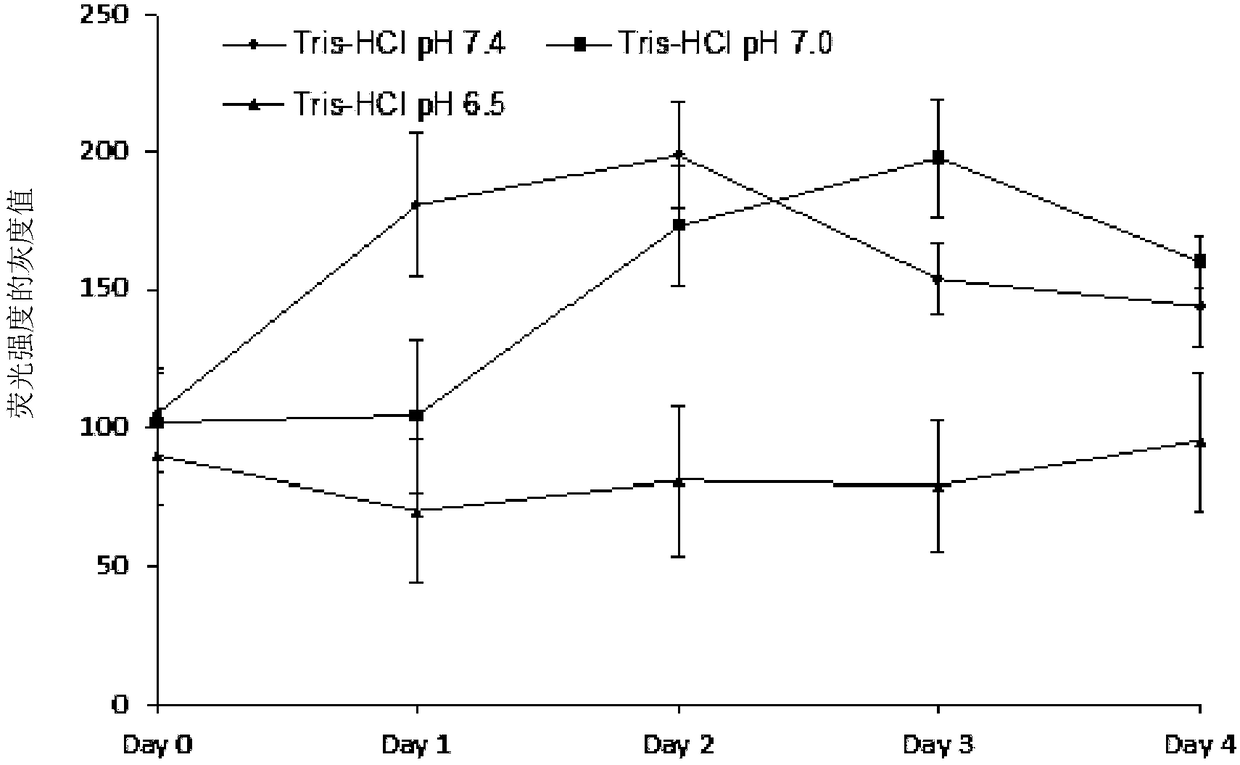
[0029] Visually distinguish the pH of the obtained fluorescent porous si...

Embodiment 2

[0031] Preparation of carboxylated porous silicon particles:

[0032] (1) using toluene as a solvent, preparing a mixed solution with a volume ratio of undecylenic acid and toluene of 1:8 to 15;

[0033] (2) Electrochemical preparation, non-ultrasonic dispersion of porous silicon particles in the above mixed solution, oil bath at 100-150 ° C, heating and reflux under nitrogen atmosphere, and reaction for 1.5-3 hours to obtain carboxylated porous silicon particles, After ultrasonication for 3-10 minutes, micron-sized porous silicon particles modified by carboxylation are obtained.

Embodiment 3

[0035] Preparation of porous silica particles modified by amination:

[0036] (1) Using DMOS (dimethyl sulfoxide) as a solvent, prepare a (3-aminopropyl)triethoxysilane DMSO solution with a volume fraction of 1 to 3%;

[0037] (2) After the ultrasonic particles are fluorescently activated in the phosphate solution, react in the above reaction solution in an anhydrous environment in a shaker for 10-30 minutes;

[0038] (3) Rinse the particles with DMSO, ethanol, and water respectively, and heat in air at 75-100° C. for 10-20 min to obtain aminated porous silicon particles.

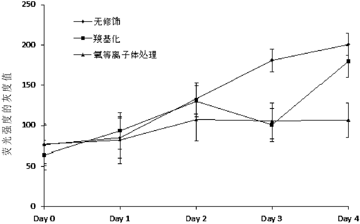
[0039] The three different porous silicon particles prepared in the above examples 1-3 were soaked in Na with a pH of 6.5 2 HPO 4 -NaH 2 PO 4 buffer (0.05M concentration). Using a UV lamp as the excitation light source, the gray value of the fluorescence intensity of porous silicon changes with time as figure 2 shown. It can be seen from the figure that under different surface chemical modifications...


PUM


Abstract

The present invention discloses applications of porous silicon particles in visualization monitoring of the wound pH value. According to the present invention, biological non-toxic porous silicon particles exhibit different fluorescence luminescent kinetic characteristics under different pH value environments, wherein different fluorescence luminescent characteristics under different pH value conditions are exhibited so as to be visible to naked eyes, the visualization monitoring is achieved, and the complex signal transmission equipment is not required so as to provide practicality and convenience; and the fluorescent material has the nano-scale pore channel structure and has the drug loading function, such that the drug can be released to treat the wound during the degradation of the material so as to simultaneously achieve the drug loading and the wound monitoring.

Description

technical field [0001] The invention relates to the application of porous silicon particles in visual monitoring of wound pH. Background technique [0002] Wound healing is a complex cell regeneration process involving a series of complex physiological and chemical reactions such as cell necrosis, shedding, and regrowth. Wound repair consists of four processes: hemostasis, inflammation, cell proliferation, and tissue remodeling. At each stage, cells undergo different biochemical reactions and produce different metabolites. Therefore, in the process of wound repair, the presence of such biomarkers represents the wound healing status, predicts the direction of the wound, and guides the subsequent treatment plan. [0003] Modern medicine often adopts empirical medicine in the process of treating wounds. The doctor administers medication to the patient's wound and formulates a follow-up treatment plan through the consultation experience. To a certain extent, this will miss t...

Claims


Application Information

Patent Timeline
Patent Type & Authority Patents(China)
IPC IPC(8): C25F3/12A61B5/1455A61B5/145B82Y40/00
CPCA61B5/14539A61B5/1455B82Y40/00C25F3/12
Inventor 邬建敏陈锡胜沃芳洁郑乐回来焱
Owner ZHEJIANG UNIV
Why Eureka
Try Eureka