Method for reducing stress of micromechanical beam membrane, and relevant low-stress membrane
A thin-film stress and micro-mechanical technology, applied in the field of micro-electromechanical systems, can solve problems such as film structure expansion, film structure rupture, device failure, etc., and achieve the effects of enhanced mechanical strength, high Young's modulus, and improved reliability
- Summary
- Abstract
- Description
- Claims
- Application Information
AI Technical Summary
Problems solved by technology
Method used
Image

Examples
Embodiment 1
[0030] A method for preparing a low-stress composite film for micromechanical beams, specifically comprising the steps of:
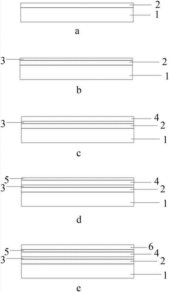
[0031] (1). A silicon wafer 1 with a crystal plane index of , a plane size of 1cm×1cm, and a thickness of 500μm is selected as the substrate. There is a silicon dioxide layer formed by thermal oxidation on the surface of the substrate. The thickness of the silicon dioxide layer is The above substrate was placed in a mixed system of concentrated sulfuric acid:hydrogen peroxide with a volume ratio of 7:3, heated and boiled for 10 minutes, then cleaned with deionized water for 15 times, then ultrasonically treated for 30 minutes, and placed in a nitrogen atmosphere at Dry at 180°C to obtain figure 1 The structure shown in a;
[0032] (2). The substrate obtained through step (1) is placed in the vacuum chamber of the electron beam evaporator to evaporate a metal titanium layer 3 with a thickness of 5nm, such as figure 1 As shown in b, the effect of the met...
Embodiment 2
[0037] A method for preparing a low-stress composite film for micromechanical beams, specifically comprising the steps of:
[0038] (1). A silicon wafer 1 with a crystal plane index of , a plane size of 1cm×1cm, and a thickness of 500μm is selected as the substrate. There is a silicon dioxide layer formed by thermal oxidation on the surface of the substrate. The thickness of the silicon dioxide layer is The above substrate was placed in a mixed system of concentrated sulfuric acid:hydrogen peroxide with a volume ratio of 7:3, heated and boiled for 10 minutes, then cleaned with deionized water for 15 times, then ultrasonically treated for 30 minutes, and placed in a nitrogen atmosphere at Dry at 180°C to obtain figure 1 The structure shown in a;
[0039] (2). Place the substrate obtained through step (1) in the vacuum chamber of the electron beam evaporator to vapor-deposit a metal titanium layer 3 with a thickness of 5 nm, such as figure 1 As shown in b, the effect of the me...
Embodiment 3
[0044]A method for preparing a low-stress composite film for micromechanical beams, specifically comprising the steps of:
[0045] (1). A silicon wafer 1 with a crystal plane index of , a plane size of 1cm×1cm, and a thickness of 500μm is selected as the substrate. There is a silicon dioxide layer formed by thermal oxidation on the surface of the substrate. The thickness of the silicon dioxide layer is The above substrate was placed in a mixed system of concentrated sulfuric acid:hydrogen peroxide with a volume ratio of 7:3, heated and boiled for 10 minutes, then cleaned with deionized water for 15 times, then ultrasonically treated for 30 minutes, and placed in a nitrogen atmosphere at Dry at 180°C to obtain figure 1 The structure shown in a;
[0046] (2). Place the substrate obtained through step (1) in the vacuum chamber of the electron beam evaporator to vapor-deposit a metal titanium layer 3 with a thickness of 5 nm, such as figure 1 As shown in b, the effect of the met...
PUM
| Property | Measurement | Unit |
|---|---|---|
| Thickness | aaaaa | aaaaa |
| Thickness | aaaaa | aaaaa |
| Thickness | aaaaa | aaaaa |
Abstract
Description
Claims
Application Information
 - R&D
- Intellectual Property
- Life Sciences
- Materials
- Tech Scout
- Unparalleled Data Quality
- Higher Quality Content
- 60% Fewer Hallucinations
Browse by: Latest US Patents, China's latest patents, Technical Efficacy Thesaurus, Application Domain, Technology Topic, Popular Technical Reports.
© 2025 PatSnap. All rights reserved.Legal|Privacy policy|Modern Slavery Act Transparency Statement|Sitemap|About US| Contact US: help@patsnap.com