
Hybrid laser welding method and device for transparent brittle materials

A brittle material, laser welding technology, applied in the direction of laser welding equipment, welding equipment, metal processing equipment, etc., can solve the problems of surface ablation, slow processing speed, cracking, etc., and achieve the effect of strong applicability, firm and reliable welding

Active Publication Date: 2018-09-28
HUAZHONG UNIV OF SCI & TECH
View PDF10 Cites 11 Cited by
  • Summary
  • Abstract
  • Description
  • Claims
  • Application Information

AI Technical Summary

Problems solved by technology

Ultrafast laser utilizes extremely high peak power density and ultrashort laser pulses to generate nonlinear absorption inside transparent and brittle materials, and melts materials at the focal point to realize micro-welding of transparent and brittle media, with high processing precision and small heat-affected zone , unbreakable, high connection strength, and space-selective processing, but this method also exhibits the following problems: (1) Although the ultrafast laser can complete instantaneous welding due to its high energy density at the focus, it is usually used Large numerical aperture microscopic objective lens focuses, the focus space range is small, and the position of the beam remains unchanged. To achieve regional welding, the beam is usually fixed. The precision two-dimensional workbench carries out welding with the movement of the material to be welded, and the processing speed is slow. From the hardware level The processing speed is limited; (2) Ultrafast laser welding usually requires the surface to be welded to be in optical contact, that is, the distance between the contact surfaces is <500nm, and there is no interference fringe when observed with the naked eye. Larger gaps will cause plasma overflow and cause surface ablation or rupture. At present, there is a special experimental research on this, and the maximum tolerance of the gap is required to be within 3μm to be effective for welding. Therefore, this method of welding is not only difficult to apply because it needs to polish and clean the surface to achieve extremely high cleanliness and smoothness. The surface is also powerless and cannot be used in engineering applications. For example, in patent CN106449439A, when using ultra-fast lasers to package glass chips, not only must the surface of the glass to be sealed be maintained at a high level, but also cannot be directly welded when the spacing is greater than 1 μm , it is necessary to add a glass piece between the two pieces of glass, and scan, package and weld the upper and lower pieces of glass and the middle glass piece respectively. The steps are cumbersome and the efficiency is low.
[0004] In addition, there is also a method for welding glass materials with multiple laser beams, such as the method and equipment for welding glass materials with multiple laser beams disclosed in patent CN107892469A. This patent uses ultrafast laser beams and continuous or long pulse laser beams The combination beam realizes the welding of two pieces of the same glass, which can weld the larger welding gap that does not meet the optical contact conditions, and realize the scanning mirror laser welding, improve the efficiency of laser welding, and realize engineering application. However, After research, it is found that the above welding methods still have the following problems: (1) The energy of the ultrafast laser beam and the continuous or long pulse laser beam will be superimposed at the weld during beam combining welding, which will cause the instantaneous temperature of the material to be too high and generate excessive heat. Stress causes poor material strength, so this welding method has high requirements for the selection of laser beam energy, and cannot be applied to higher energy laser beams; (2) Ultrafast laser and continuous or long pulse laser simultaneously Effect, when the ultrafast laser power density is too high, it will cause ablation of the material and affect the welding effect of the material. Therefore, it is necessary to control the power of the ultrafast laser during beam welding, which cannot be applied to higher power lasers.
Therefore, under the limitation of the above-mentioned superposition effect and ablation effect, although it claims that it can realize the welding of two pieces of glass with a contact gap greater than 5 μm, in fact, after research, it is found that it can only achieve the welding of two same materials with a maximum gap of about 12 μm.

Method used


Image

  • Hybrid laser welding method and device for transparent brittle materials

Examples


Embodiment 1

[0044] Using a Nd:YAG picosecond laser with an output wavelength of 1064nm, a pulse width of 10ps, a maximum output power of 90W, and a pulse repetition frequency of 1MHz, and a fiber continuous laser with an output wavelength of 1064nm and a maximum output power of 100W, two natural stacked The ordinary soda-lime glass with a size of 50×25mm and a thickness of 1mm is placed, and the gap between two pieces of glass stacked is 15μm. The focus of the picosecond laser and the continuous laser are both in the gap between the two natural stacked glasses. S speed scans the initial weld of a rectangular seal with a length of 20mm and a width of 10mm; then move the welding material under the continuous laser scanning unit, start the continuous laser, output a 40W power beam, and pass through the scanning galvanometer and the f-θ flat-field scanning lens. Seal the initial weld along a rectangle with a length of 20mm and a width of 10mm, and perform scanning welding at a speed of 10mm / s...

Embodiment 2

[0046] Using a Nd:YAG picosecond laser with an output wavelength of 1064nm, a pulse width of 10ps, a maximum output power of 90W, and a pulse repetition frequency of 1MHz, and a fiber continuous laser with an output wavelength of 1064nm and a maximum output power of 100W, two stacked Dissimilar glass with a size of 60×40mm and a thickness of 2mm. The upper layer is quartz glass and the lower layer is soda-lime glass. The gap between the two glasses is 20μm. The composite laser welding method for brittle materials is adopted. The focus of the picosecond laser and the continuous laser are both in the gap between two pieces of natural stacked glass. -θ flat-field scanning lens, scanning the rectangular sealing initial welding seam with a length of 40mm and a width of 30mm at a speed of 3000mm / s to form a 40×30mm rectangular white translucent initial welding seam; after that, the welding material is moved to the continuous laser scanning unit Below, start the continuous laser to o...

Embodiment 3

[0048] Use a Nd:YAG picosecond laser with an output wavelength of 1064nm, a pulse width of 10ps, a maximum output power of 90W, and a pulse repetition frequency of 1MHz, and a fiber continuous laser with an output wavelength of 1064nm and a maximum output power of 100W to weld two stacks. Quartz glass with a size of 50×50mm and a thickness of 1.5mm is placed, and the gap between two pieces of glass stacked is 25μm. Using the composite laser welding method for brittle materials, the focus of the picosecond laser and the continuous laser are both in the gap between the two natural stacked glasses. -θ flat-field scanning lens, scanning the square sealing initial welding seam with a length of 40mm and a width of 40mm at a speed of 4000mm / s to form a 40×40mm square white translucent initial welding seam; after that, the welding material is moved to the continuous laser scanning system Below, start the continuous laser to output a continuous beam of 80W power, pass through the scann...


PUM

PropertyMeasurementUnit
shear strengthaaaaaaaaaa

Abstract

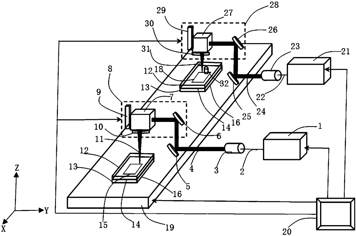
The invention belongs to the technical field of laser processing, and particularly discloses a hybrid laser welding method and device for transparent brittle materials. The method comprises the following steps: S1, focusing an ultrafast laser beam at a position where two to-be-welded transparent brittle materials are in contact with each other to form a white semi-transparent initial weld joint toimplement preliminary welding; and S2, focusing a continuous laser beam at the position of the white semi-transparent initial weld joint to implement final welding. The device comprises an ultrafastlaser beam generation module and a continuous laser beam generation module, wherein the ultrafast laser beam generation module is used for implementing initial welding; and the continuous laser beam generation module is used for implementing final welding. By the hybrid laser welding method and device for transparent brittle materials, firm welding of the two transparent brittle materials with a large contact gap can be realized. The hybrid laser welding method and device for transparent brittle materials have the advantages of firm and reliable welding, wide application range, simple technological process and the like.

Description

technical field [0001] The invention belongs to the technical field of laser processing, and more specifically relates to a method and device for composite laser welding of transparent and brittle materials. Background technique [0002] Transparent and brittle materials such as glass, silicon, and sapphire play an indispensable role in daily life and scientific research and production because of their stable chemical properties and excellent physical properties including light transmission, insulation, corrosion resistance, and high hardness. role. In many applications, multiple transparent and brittle material parts that are assembled and sealed together are used, such as the assembly of lenses in optics, which require multiple lenses to withstand a specific optical power density passing through the aperture; optoelectronics In the packaging of semiconductor sensors corresponding to specific spectra, an insulating shell that is transparent to the signal light of the corre...

Claims


Application Information

Patent Timeline
Patent Type & Authority Applications(China)
IPC IPC(8): B23K26/03B23K26/24B23K26/324B23K26/70
CPCB23K26/032B23K26/24B23K26/324B23K26/702Y02P40/57
Inventor 段军白克强陈航曾晓雁
Owner HUAZHONG UNIV OF SCI & TECH
Learn More