A kind of method for preparing nano-silicon carbide at low temperature
A nano-silicon carbide and low-temperature technology, applied in the direction of silicon carbide, chemical instruments and methods, carbides, etc., can solve the problems of easy agglomeration and low yield, and achieve the effect of simple process and convenient large-scale production
- Summary
- Abstract
- Description
- Claims
- Application Information
AI Technical Summary
Problems solved by technology
Method used
Image
Examples
Embodiment 1
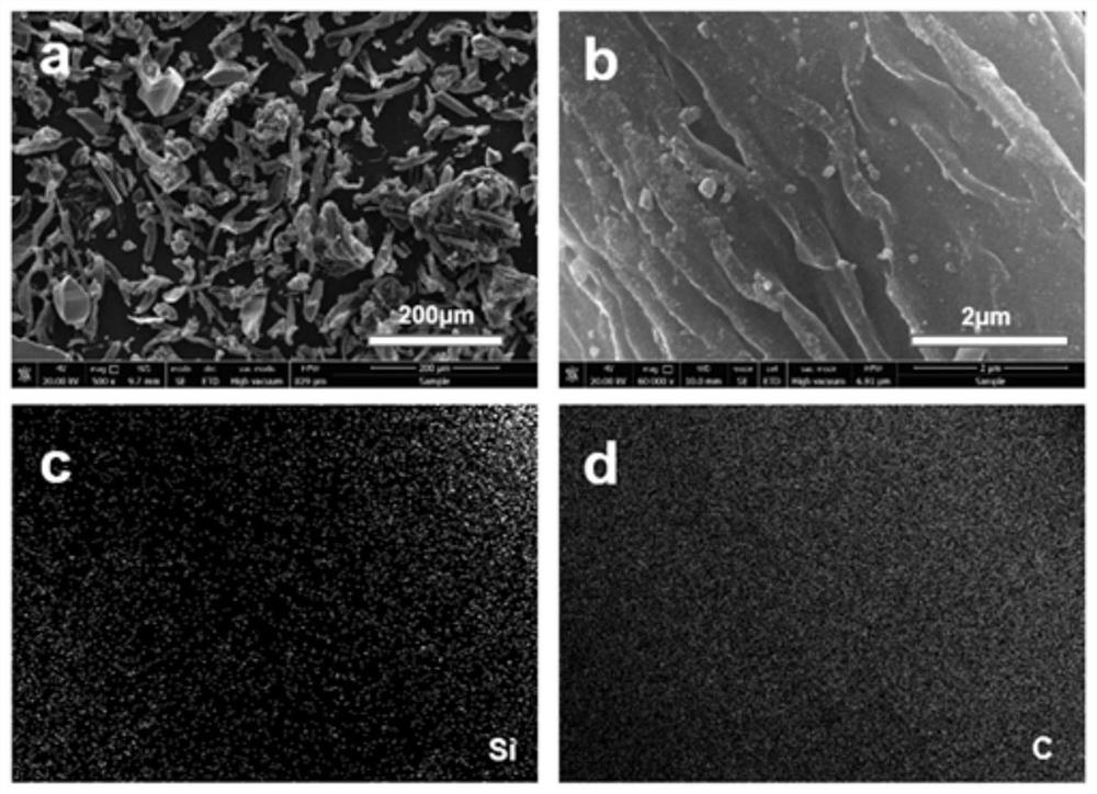
[0027] The first confinement effect: Weigh a certain amount of cellulose and nano-silica (mass ratio is 3:1), put it in a 100ml ball mill jar, mill it at 450rpm for 2h, and then put the mixture in a tube furnace for pyrolysis treatment . The treatment temperature is 600°C, the time is 4h, and the heating rate is 5°C min -1 . The obtained sample was naturally cooled to room temperature to obtain a silica / carbon composite. figure 1 (a) and (b) are scanning electron microscope pictures of the silicon dioxide / carbon composite prepared in this embodiment, from figure 1 In the energy spectrum scanning images of (c) and (d), it can be seen that silicon is evenly distributed on the carbon skeleton, forming a good composite structure with the carbon skeleton.
[0028] The second confinement effect: mechanically mix the silica / carbon composite obtained above with metal magnesium according to a certain mass ratio (1:1), then transfer the mixture to a stainless steel reactor, and final...
Embodiment 2
[0030] The first confinement effect: the same as in Embodiment 1.
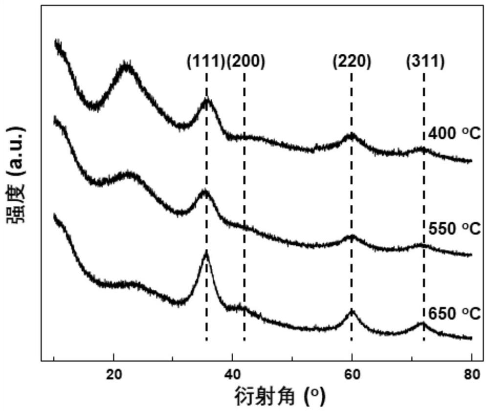
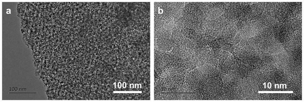
[0031] The second confinement effect: the reduction temperature is 650°C, other conditions are the same as in Example 1, and the XRD diffraction pattern of the obtained nano-SiC is as follows figure 2 As shown, compared with the standard card JCPDS29-1129, its 2θ=35.6°, 60° and 71.7° correspond to the (111), (220) and (311) crystal planes of SiC, respectively. image 3 (a) and (b) are the TEM images of the sample, respectively. It can be seen that the sample has a certain pore structure at low resolution, which is mainly due to the SiO 2 Pores left after deoxygenation reacts with the carbon skeleton. The (111) interplanar spacing of SiC can be measured as 0.252nm in the high-resolution transmission electron microscope pictures. Figure 4 It is a scanning electron microscope picture of the sample, and it can be seen that it has an obvious mesoporous structure. Figure 5 (a) is the nitrogen adsorption-desorp...
Embodiment 3
[0033] The first confinement effect: the same as in Embodiment 1.
[0034] The second confinement effect: the reduction temperature is 400°C, other conditions are the same as in Example 1, and the XRD diffraction pattern of the obtained nano-SiC is as follows figure 2 As shown, compared with the standard card JCPDS29-1129, its 2θ=35.6°, 60° and 71.7° correspond to the (111), (220) and (311) crystal planes of SiC, respectively.
PUM
| Property | Measurement | Unit |
|---|---|---|
| particle diameter | aaaaa | aaaaa |
| particle diameter | aaaaa | aaaaa |
| lattice spacing | aaaaa | aaaaa |
Abstract
Description
Claims
Application Information
 - R&D
- Intellectual Property
- Life Sciences
- Materials
- Tech Scout
- Unparalleled Data Quality
- Higher Quality Content
- 60% Fewer Hallucinations
Browse by: Latest US Patents, China's latest patents, Technical Efficacy Thesaurus, Application Domain, Technology Topic, Popular Technical Reports.
© 2025 PatSnap. All rights reserved.Legal|Privacy policy|Modern Slavery Act Transparency Statement|Sitemap|About US| Contact US: help@patsnap.com


