

Efficient and stable planar heterojunction perovskite solar cell and preparation method thereof
A solar cell and perovskite technology, applied in circuits, electrical components, photovoltaic power generation, etc., can solve the problems of insufficient photoelectric conversion efficiency, easy agglomeration, high energy consumption, etc., and achieve the effect of good light absorption characteristics
- Summary
- Abstract
- Description
- Claims
- Application Information
AI Technical Summary
Problems solved by technology
Method used
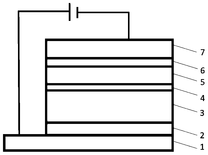
Image

Examples
Embodiment 1
[0031] 1) The commercially purchased ITO was ultrasonically cleaned in acetone, ITO cleaning agent, deionized water, and isopropanol. After cleaning, it was blown dry with nitrogen, and after ozone treatment for 10-30 minutes, put it into a petri dish and transfer it to a glove box (N 2 under gas nitrogen) for standby;
[0032] 2) Form a film of PTAA on ITO with a spin coating process, the film thickness is about 5-20nm, and anneal on a hot stage at 60-100°C for 10 minutes;
[0033] 3) 1.2-1.3mol / L of PbI 2 :MAI (1.2:0.3) mixed solution is spin-coated on the PTAA film layer with the speed of 6Krpm, and after the spin-coating process film is formed, the MAI solution of 40mg / ml is drop-coated from top to bottom. Then the film was placed on a hot stage at 100°C and annealed for 10 minutes. where PbI 2 : the solvent of the MAI mixed solution is DMF, and the MAI solution is dissolved in Virahol;
[0034] 4) Spin-coat the chlorobenzene solution of PEO on the perovskite active laye...
Embodiment 2
[0039] 1) The commercially purchased FTO was ultrasonically cleaned in acetone, FTO cleaning agent, deionized water, and isopropanol. After cleaning, it was blown dry with nitrogen, and after ozone treatment for 10-30 minutes, put it into a petri dish and transfer it to a glove box (N 2 under gas nitrogen) for standby;
[0040] 2) Form a film of PEDOT:PSS on FTO with a spin coating process, the film thickness is about 5-30nm, and anneal at 70-130°C for 15 minutes on a hot stage;
[0041] 3) the PbI of 1mol / L 2 :MAI (1:1) mixed solution was spin-coated on the PEDOT:PSS film layer at a speed of 4Krpm. After the spin-coating process was formed, the film was placed on a hot stage at 100°C and annealed for 10 minutes. where PbI 2 : The solvent of the MAI mixed solution is DMF;
[0042] 4) Spin-coat the chlorobenzene solution of PEO on the perovskite active layer with a thickness of about 1-10 nm, and anneal on a hot stage at 70-100 ° C for 10 minutes;
[0043] 5) Spin-coat the ...
Embodiment 3
[0047] 1) The commercially purchased FTO was ultrasonically cleaned in acetone, FTO cleaning agent, deionized water, and isopropanol. After cleaning, it was blown dry with nitrogen, and after ozone treatment for 10-30 minutes, put it into a petri dish and transfer it to a glove box (N 2 under gas nitrogen) for standby;
[0048] 2) Put V 2 o 5 The precursor solution is formed on the FTO by spin coating process, the film thickness is about 10-20nm, and annealed on the hot stage at 150°C for 30 minutes;
[0049] 3) 889mg / ml FAPbI3, 33mg / ml MAPbBr3 and 33mg / ml MACl were dissolved in a mixed solvent of DMF / DMSO (8:1v / v), and then spin-coated on the V2O5 film. In the spin coating process, two-step spin coating is adopted, the first section is 1000 rotations for 5 seconds, the second section is 5000 rotations for 20 seconds, and 100ul chlorobenzene is drip-coated on the perovskite film at the second section 15 seconds to promote film crystallization . Then the film was placed on ...
PUM
 Abstract
Description
Claims
Application Information