Garbage pyrolysis waste gas purification system and process

A waste gas purification system and garbage technology, applied in incinerators, lighting and heating equipment, combustion product treatment, etc., can solve the problem of failure to effectively utilize the calorific value of flue gas, difficulty in meeting the requirements of environmental friendliness, and complicated treatment processes, etc. problem, to achieve the effects of lower gas temperature, good sulfur resistance, and large adsorption capacity

Pending Publication Date: 2021-11-02
KUNMING UNIV OF SCI & TECH
View PDF3 Cites 0 Cited by
  • Summary
  • Abstract
  • Description
  • Claims
  • Application Information

AI Technical Summary

Problems solved by technology

[0008] According to the above three patented technologies for purification of waste incineration flue gas, it can be found that the designed system or method involves a spray device, and the spray device is used to clean the flue gas in waste incineration to remove acid gas or other Water-soluble organic pollutants, in which the spray liquid is an alkaline solution, which is likely to prod

Method used


Image

  • Garbage pyrolysis waste gas purification system and process

Examples


Example Embodiment

[0042] Example 1

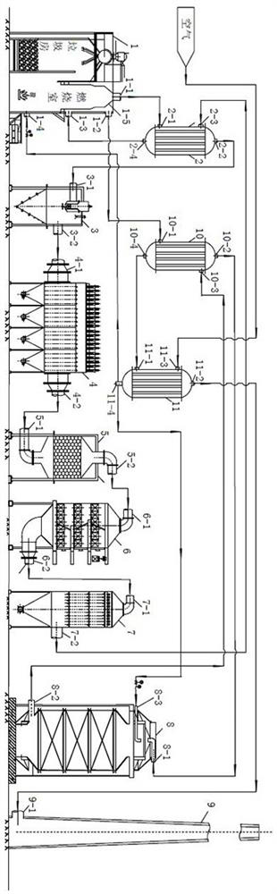
[0043] The temperature in the combustion chamber of the waste combustion chamber 1 is 700℃, the temperature of the flue gas at the outlet is 180℃, and the flow rate of the flue gas is 1000m 3 / h, the flue gas enters the heat exchanger I for heat exchange and cooling, and the temperature is lowered to 122 °C; then the flue gas passes through the cyclone dust collector 3, the electrostatic collection and dust removal composite tar removal device 4, the activated carbon adsorption tower 5, and the dry desulfurization reactor 6. The dry dechlorination reactor 7 is processed to obtain a low-temperature preliminary purified gas, and the gas temperature is 60 °C;

[0044] Wherein, the desulfurizing agent used in the dry desulfurization reactor 6 is a mixture of 27.5g calcium oxide, 5g iron oxide, 7.5g calcium carbonate, 5g carbon slag, 2.5g cement and 8.3g silica sol (wherein SiO 2 30 wt.%) in a polyethylene beaker, grinding and mixing, and then dropwise add 30 mL...

Example Embodiment

[0048] Example 2

[0049] The temperature in the combustion chamber of the waste combustion chamber 1 is 700℃, the temperature of the flue gas at the outlet is 183℃, and the flow rate of the flue gas is 1500m 3 / h, the flue gas enters the heat exchanger I for heat exchange and cooling, and the temperature is lowered to 128 °C; then the flue gas passes through the cyclone dust collector 3, the electrostatic collection and dust removal composite tar removal device 4, the activated carbon adsorption tower 5, and the dry desulfurization reactor 6. The dry dechlorination reactor 7 is processed to obtain a low-temperature preliminary purified gas, and the gas temperature is 62 °C;

[0050] Wherein, the desulfurizing agent used in the dry desulfurization reactor 6 is a mixture of 27.5g calcium oxide, 5g iron oxide, 7.5g calcium carbonate, 5g carbon slag, 2.5g cement and 8.3g silica sol (wherein SiO 2 30 wt.%) in a polyethylene beaker, grinding and mixing, and then dropwise add 30 mL...

Example Embodiment

[0054] Example 3

[0055] The combustion chamber temperature of waste combustion chamber 1 is 700°C, the outlet flue gas temperature is 185°C, and the flue gas flow rate is 2000m 3 / h, the flue gas enters the heat exchanger I for heat exchange and cooling, and the temperature is lowered to 130 °C; then the flue gas passes through the cyclone dust collector 3, the electrostatic collection and dust removal combined tar removal device 4, the activated carbon adsorption tower 5, and the dry desulfurization reactor 6. The dry dechlorination reactor 7 is processed to obtain a low-temperature preliminary purified gas, and the gas temperature is 65 °C;

[0056] Wherein, the desulfurizing agent used in the dry desulfurization reactor 6 is a mixture of 28.5g calcium oxide, 2.5g magnesium oxide, 5g iron oxide, 1.5g manganese oxide, 7.5g calcium carbonate, 2.5g cement and 8.3g silica sol (wherein SiO 2 30 wt.%) in a polyethylene beaker, grinding and mixing, and then dropwise add 30 mL of...


PUM


Abstract

The invention discloses a garbage pyrolysis waste gas purification system and process. The system comprises a garbage combustion chamber, a heat exchanger I, a cyclone dust collector, an electric collection dust removal composite tar removal device, an activated carbon adsorption tower, a dry desulfurization reactor, a dry dechlorination reactor, a catalytic combustor, a chimney, a heat exchanger II and a heat exchanger III. The process comprises the steps of flue gas primary purification, heat exchange heating and combustion purification, and heat exchange cooling and combustion air heating. Flue gas generated by garbage pyrolysis is subjected to multiple heat exchange with dechlorination reaction gas, catalytic combustion gas and air through the heat exchangers, waste heat in different waste gases can be fully utilized, the air is heated to a certain temperature and then enters the garbage combustion chamber to perform pyrolysis treatment on garbage, and the purposes of environmental protection and energy conservation are achieved. According to the system and the process, pollutants, such as particulate matters, smoke dust, dioxin, tar, SO2, HCl and other irritant gases, in the waste combustion flue gas can be effectively removed, and the treated tail gas can be discharged up to standard.

Description

technical field [0001] The invention belongs to the technical field of waste pyrolysis waste gas purification and treatment, and in particular relates to a waste pyrolysis waste gas purification system and a process. Background technique [0002] With the rapid development of urbanization, the phenomenon of wasting resources to improve the economy is endless, and more and more cities are facing the dilemma of garbage siege. The large amount of solid waste generated in daily life in cities has brought enormous pressure to the environment. These urban wastes will produce a large number of harmful components during the collection, transportation and treatment process, which will pollute the atmosphere, soil, water sources, etc., which is a domestic problem. one of the major environmental problems. At present, the treatment of domestic municipal solid waste mainly includes three technologies: landfill, composting and incineration. In addition to occupying land, landfill leacha...

Claims


Application Information

Patent Timeline
IPC IPC(8): F23G5/027F23G5/44F23G5/46F23G7/07F23J15/00F23J15/02
CPCF23G5/027F23G5/44F23G5/46F23G7/07F23J15/006F23J15/027F23J2215/20F23J2217/40F23J2219/30
Inventor 张秋林陈建军宁平高连昀李琳娜姜曼田仔梦李志宇田笑言
Owner KUNMING UNIV OF SCI & TECH
Why Eureka
Try Eureka