
Abrasion resistant coated process of miniature cutter

A technology of cutting tools and process methods, which is applied to the field of forming thin films on the surface of micro-milling cutters, can solve problems such as difficult to apply wear-resistant coatings on micro-tools, poor wear and corrosion resistance properties, public safety and environmental control concerns, etc. Achieve the effects of wide application range, good adhesion, and avoid toughness reduction

Inactive Publication Date: 2004-12-08
COSMOS VACUUM TECH CORP
View PDF2 Cites 6 Cited by
  • Summary
  • Abstract
  • Description
  • Claims
  • Application Information

AI Technical Summary

Problems solved by technology

[0003] The existing cutting tool wear-resistant coating technology is divided into two categories: chemical vapor deposition (Chemical Vapor Deposition, CVD) method and physical vapor deposition method. The former is usually vacuum coated at high temperature, and the process temperature is generally 400 ° C to 1200 ° C Left and right, in order to carry out the film deposition reaction of transition metal nitride (Nitride), carbide (Carbide) or carbonitride (Carbon-nitride), such as disclosed in US Pat. The method is a relatively low-temperature process method, and its temperature range is as high as 400-900 ° C. Although the ZrCN wear-resistant layer can be deposited, because the process temperature is too high, it will cause damage and softening on the tip of the micro-tool. In addition, the reaction used Gases containing metal halides are highly toxic, so there are concerns about public safety and environmental control
[0004] In the physical vapor deposition method, the most important one is sputtering or sputtering (Sputtering) method, and its temperature can be controlled below 400 ° C, such as the carbides and nitrides of some transition metals disclosed in British Patent GB2226334 Or oxide sputtering process, these coatings are limited to metal substrates with Vickers' Hardness less than 300, if the Vickers' Hardness of the substrate is greater than 300, it will cause the coating and Poor adhesion between substrates resulting in poor wear and corrosion properties
Therefore, the sputtering technology with small ion energy is still difficult to apply to the wear-resistant coating of micro-tools

Method used

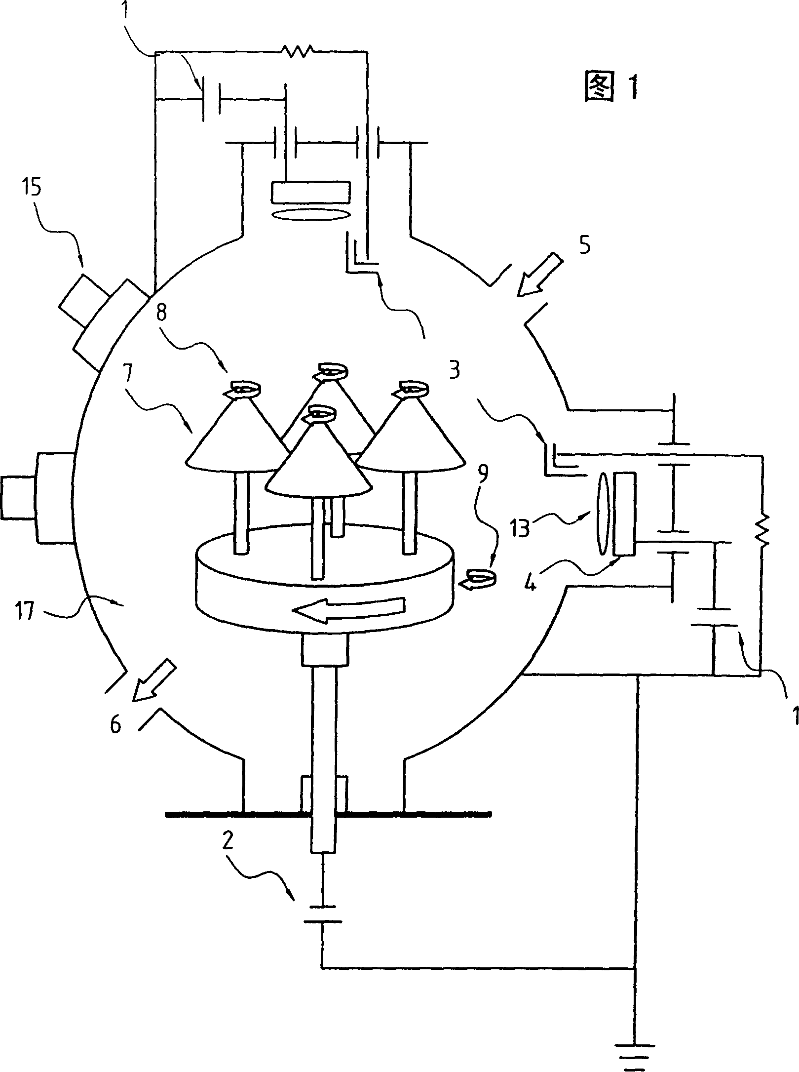
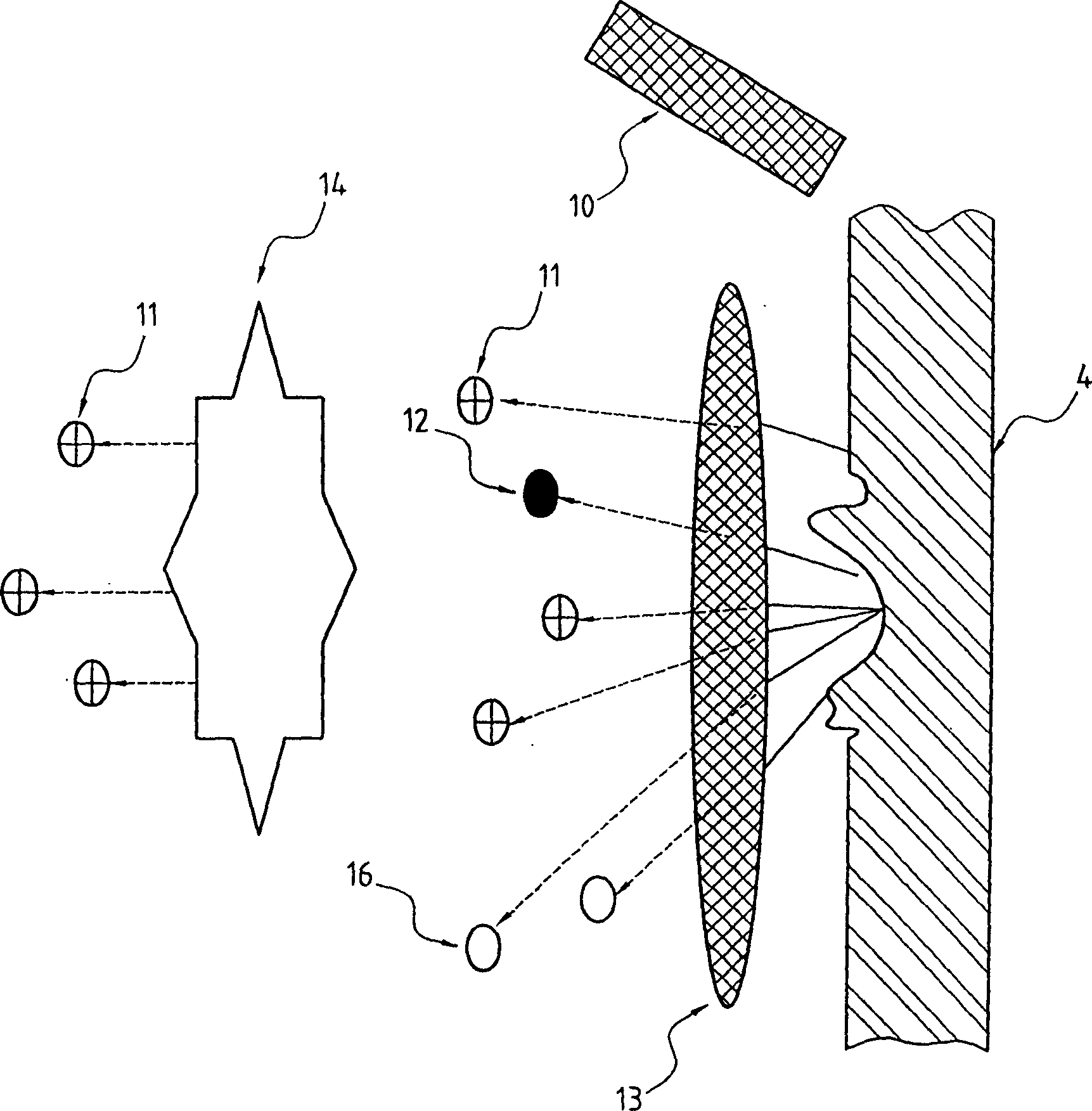

Image

  • Abrasion resistant coated process of miniature cutter
  • Abrasion resistant coated process of miniature cutter
  • Abrasion resistant coated process of miniature cutter

Examples


Embodiment 1

[0050] The object to be plated is a micro milling cutter, the base material of the micro milling cutter is tungsten carbide ceramic gold, the diameter of the shank is 3.175mm, the diameter of the blade is 1.0mm, and the effective blade length is 5mm. The operating temperature of the membrane is from 250°C to 400°C.

[0051] Milling cutter sample

[0052] Table 1: Milling cutter life test table

Embodiment 2

[0054] The object to be plated is a micro milling cutter, the base material of the micro milling cutter is tungsten carbide sintered superhard alloy, the diameter of the shank is 3.175mm, the diameter of the blade is 1.5mm, and the effective blade length is 8mm. The target materials used in the process are Zr and Hf alloys. The operating temperature for coating is 210°C-390°C.

[0055] Milling cutter sample

[0056] Table 2: Milling cutter life test table

Embodiment 3

[0058] The object to be plated is a micro drill bit, the base material of the micro milling cutter is tungsten carbide ceramic gold, the diameter of the shank is 3.175mm, the diameter of the drill tail is 0.3mm, the effective length is 5.5mm, the coating layer is ZrCN film, and the operating temperature for coating is 120 ℃-280℃.

[0059] Micro drill sample

[0060] Table 3: Cpk value of micro-drill drilling test


PUM

PropertyMeasurementUnit
diameteraaaaaaaaaa
thicknessaaaaaaaaaa

Abstract

This invention relates to a process to coat a wear resistance film with thickness of 0.5 - 3um onto miniature machining tools, which can be sintered tungsten carbide or tungsten carbide cermet milling cutters or drill bits with shank diameters <4mm. Its constituent is ZrHfCN with Hf content of 0 - 10 wt%. It has good adhesion strength and can works at higher speed and with longer service life. Actually, it can make service life of tools 1.5 - 3 times long in machining printed circuit boards.

Description

technical field [0001] The present invention involves using the principles of physical vapor deposition (Physical Vapor Deposition, PVD), ion bombardment cleaning and ion-assistant coating (ion-assistant coating) to coat multi-element ultrafine ion particles on the surface of a micro-milling cutter to form a film. Especially a multi-element coating of zirconium (Zr), hafnium (Hf), carbon (C), nitrogen (N) on tungsten carbide sintered superhard alloy (Sintered Tungsten Carbide) or tungsten carbide ceramic gold (Tungsten Carbide Cermet) ) on the micro-drill and milling cutter. Background technique [0002] Micro-sized drills (Drills) and milling cutters (Routers) with a Shank Diameter of 3.175 mm are often installed on drilling machines and milling machines to drill holes on printed circuit board (PCB) substrate materials and Cutting, these substrates are basically made of glass fiber (Glass Fiber), some even add multi-layer copper foil or polytetrafluoroethylene (PTEF), so t...

Claims


Application Information

Patent Timeline
Patent Type & Authority Applications(China)
IPC IPC(8): C23C14/06C23C14/34
Inventor 赖泰锽
Owner COSMOS VACUUM TECH CORP
Learn More