
Method for manufacturing low-temperature polysilicon thin-film transistor

A polysilicon thin film and thin film transistor technology, which is applied in semiconductor/solid-state device manufacturing, optics, instruments, etc., can solve problems such as poor step coverage, easy generation of holes, and differences in protection capabilities, so as to improve electrical performance and reliability , good ladder coverage, and increased protection

Inactive Publication Date: 2005-01-19
TPO DISPLAY
View PDF0 Cites 19 Cited by
  • Summary
  • Abstract
  • Description
  • Claims
  • Application Information

AI Technical Summary

Problems solved by technology

However, as far as the commonly used dielectric layer materials are concerned, they often cannot meet the above two requirements at the same time.
Take the silicon-oxygen layer and silicon-nitride layer commonly used in general semiconductor technology or display panel technology as an example. Although the silicon-nitride layer has good protection ability and can resist the penetration of water vapor and metal ions, its high dielectric constant is easy to It causes parasitic capacitance and signal delay, and is not suitable as an interlayer dielectric layer. Although the silicon-oxygen layer has a low dielectric constant and will not cause signal delay, its protection ability is comparable to that of the aforementioned silicon nitride layer. Layers are significantly different and cannot provide a good protection against
[0009] In addition, silane or tetraethoxysilane (tetra-ethyl-ortho-silicate, TEOS) can be used as a silicon source to form two different types of silicon oxide layers, that is, The so-called silane-based silicon oxide layer (silane-based silicon oxide) or TEOS-based silicon oxide layer (TEOS-based silicon oxide), where the former contains significant hydrogen atoms, can be used as a device A source of hydrogenated hydrogen atoms to repair defects in polysilicon films, but due to its poor step coverage, it is easy to generate holes. Although the latter has better step coverage during deposition, it cannot provide hydrogenation. The hydrogen atom source of the process, that is, another hydrogenation process needs to be provided, which will greatly increase the equipment cost and production time of the hydrogenation process
[0010] As mentioned above, in various existing technologies, there is no one method that can produce not only good interface characteristics and high initial voltage stability, but also better barrier and anti-blocking capabilities for water vapor and metal ions. At the same time, it has an interlayer dielectric layer with a high breakdown voltage

Method used


Image

  • Method for manufacturing low-temperature polysilicon thin-film transistor
  • Method for manufacturing low-temperature polysilicon thin-film transistor
  • Method for manufacturing low-temperature polysilicon thin-film transistor

Examples


Embodiment Construction

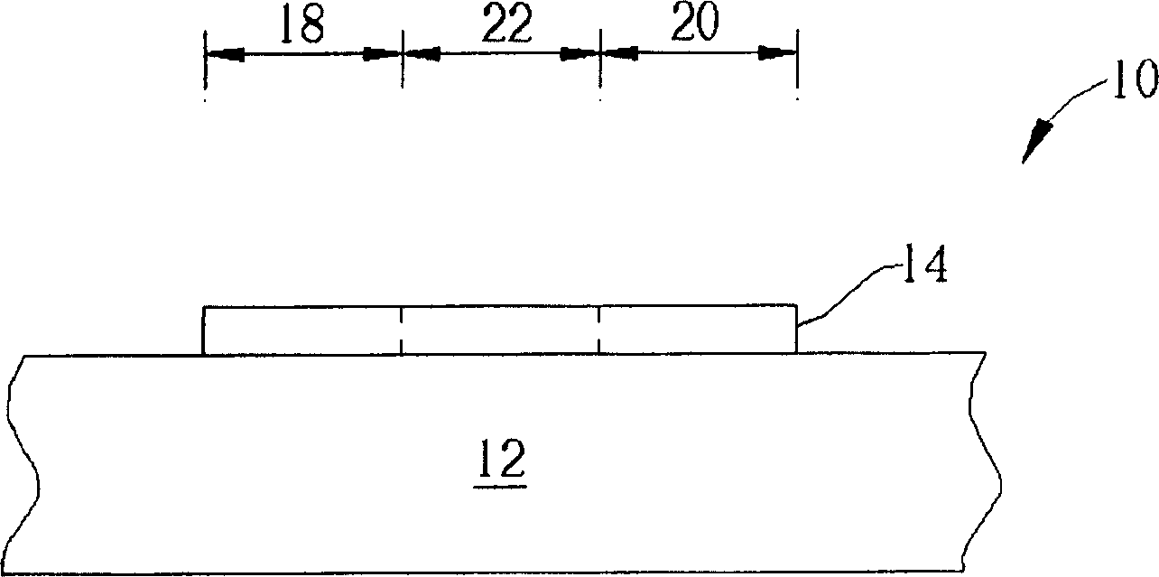
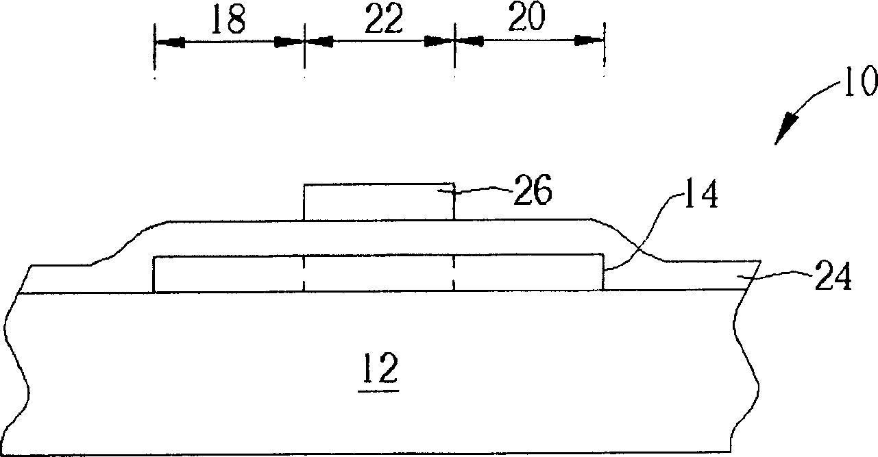
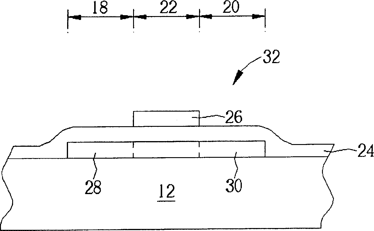
[0039] Please refer to Figure 5 to Figure 8 , Figure 5 to Figure 8 It is a schematic diagram of a method for fabricating a low-temperature polysilicon thin film transistor according to the present invention. As mentioned above, a display panel usually includes a plurality of low temperature polysilicon thin film transistors to respectively drive the pixel electrodes on the display panel. For the convenience of illustration, only one low temperature polysilicon thin film transistor is represented in the following figures. Such as Figure 5 As shown, a chemical vapor deposition process or a sputtering process is first performed to form an amorphous silicon film (not shown) with a thickness of about 500 angstroms on a display panel 110, and an excimer laser annealing process (excimer laser annealing process) to recrystallize the amorphous silicon thin film into a polysilicon thin film 114, and then perform a first photolithography and etching process to pattern the polysilico...


PUM

PropertyMeasurementUnit
thicknessaaaaaaaaaa
thicknessaaaaaaaaaa
thicknessaaaaaaaaaa

Abstract

The invention discloses a low temperature polycrystalline silicon thin film transistor making method, firstly forming a polycrystalline silicon thin film, a grid insulating layer and a grid on a substrate surface, successively forming a source and a drain around the gird, then making two plasma enhancement chemical gas phase deposition processes to respectively form a silicon nitride layer and a silicone layer with tetraethoxy silane as the principal covering the grid and the polycrystalline silicon thin film surface, and finally forming a contact hole above the source and drain, respectively and filling an electric conduction layer to connect with them, respectively.

Description

technical field [0001] The present invention relates to a method for manufacturing an interlayer dielectric layer (interlayer dielectric layer) of a low temperature polysilicon thin film transistor (LTP TFT), in particular to a composite interlayer dielectric layer (interlayer dielectric layer) layer, ILDlayer) low temperature polysilicon thin film transistor manufacturing method. Background technique [0002] In today's flat panel display technology, liquid crystal display (LCD) is one of the most mature technologies, which are used in mobile phones, digital cameras, video cameras, notebook computers and even monitors that are common in daily life. Goods produced by technology. However, with the improvement of people's requirements for the visual experience of displays and the continuous expansion of new technology application fields, flat-panel displays with higher image quality, high resolution, high brightness and low price have become the focus of future display techno...

Claims


Application Information

Patent Timeline
Patent Type & Authority Applications(China)
IPC IPC(8): G02F1/136H01L21/336
Inventor 林辉巨
Owner TPO DISPLAY
Learn More