Electrically conductive electret and associated electret-based power source and self-powered structure

a technology of electrets and electrical conductors, applied in the field of electrets, can solve the problems of inadequate public safety of nuclear reactors, fire hazards, and energy remains a significant issue all over the world

Active Publication Date: 2021-08-03
CHUNG DEBORAH DUEN LING
View PDF32 Cites 0 Cited by
  • Summary
  • Abstract
  • Description
  • Claims
  • Application Information

AI Technical Summary

Problems solved by technology

In spite of the large variety of existing power sources, energy remains a significant issue all over the world.
Examples of issues include the greenhouse gas emission associated with the burning of fossil fuels, the oil spills associated with offshore oil wells, the fires due to oil / gas leakage from oil / gas pipelines, the environmental pollution associated with the disposal of batteries and supercapacitors, the fire hazard of some batteries and supercapacitors, the inadequate public safety of nuclear reactors, the high cost of photovoltaics (solar cells) in the absence of government subsidies, the cost (and sometimes difficulty and inadequate safety) of transporting the energy from the place of generation of the particular form of energy to the place of energy usage (with the difficulty stemming from the required energy transportation infrastructure, such as pipelines), etc.
In other words, the electret produced by the poling does not provide a truly permanent electric dipole.
The need to repole greatly reduces the suitability for practical use.
As a consequence, DC electric current cannot flow continuously through these electrets.
A current pulse is less useful and less easy to detect than a continuous current.
However, without a time-varying charge magnitude (i.e., without a time-varying stimulus), the electret of the prior art (acting as a capacitor) is not able to provide an AC current, but merely a short DC current pulse, as explained above.
Without a time-varying stimulus, a piezoelectric material is not able to provide an AC current, but merely a short DC current pulse.
As a result, these electrets essentially cannot provide electric power.
In the absence of a time-varying stimulus, an electret involving a low-conductivity or nonconductive material cannot serve as an electrical power source (whether DC or AC).
However, the electric power obtained is low, ranging typically from 1 to 100 μW.
The embedment or attachment of a device (e.g., a battery) or device components (e.g., the anode, cathode and electrolyte of a battery) suffers from (i) the inadequate durability of the device (with the device being capable of a service life that is short compared to the intended service life, perhaps decades, of the structure), (ii) the high cost of the device or device components, (iii) the toxicity of some of the device components, and (iv) the non-applicability of the technology to existing structures, which do not have such embedment or attachment.
The non-applicability furthermore means that only new structures can benefit from the technology, thus greatly limiting the breadth of the application.
In case of the embedment of a device or device components, additional disadvantages are the difficulty of repair and the loss in mechanical performance of the structure.
Structures may degrade during use, improper usage, weathering (by wind, rain, ocean waves, heat, low temperatures, temperature excursions, etc.), accidents (such as collisions), natural events (such as lightning, storms, hurricanes and earthquakes).
This is because the degradation (e.g., crack formation, void formation, mass loss, etc.) commonly occurs and affects not only the operation using the material, it can also cause hazards.
Structures encounter stress and / or strain during use.
The use of such sensors is associated with high cost, low durability, limited sensing volume and mechanical property loss.
Due to the special formulation, the material is not a conventional material that is widely used.
As a result, piezoelectricity-based structural self-sensing is only applicable to structures that have the particular material design and is not broadly applicable to structures in general.
In the measurement of such small resistance changes, an adequate level of reliability is difficult to achieve in the absence of expensive high-performance electronics.
The measurement of a high resistance requires a high voltage, which can be practically infeasible or difficult.
This limits the range of materials that are effective for providing piezoresistivity-based sensing.
The presence of a continuous conductive path greatly decreases the resistivity of the composite material.
As a result, piezoresistivity-based structural self-sensing is only applicable to structures that have the particular material design and is not broadly applicable to structures in general.
The loss in mechanical performance due to the presence of the embedded device or embedded device components is partly because the device or device component disrupts or weakens the structure.
In case of the device being a battery, the loss in mechanical properties is also partly because the polymer matrix of the multifunctional structural composite not only serves to bind the reinforcing fibers together, but also serves as an electrolyte.
A polymer matrix that is capable of serving as an electrolyte is mechanically inferior to one that is typically used for polymer-matrix structural composites.
As a consequence, the mechanical properties of polymer-matrix structural composite materials that can render the battery function are inferior to those that serve only the structural function.
Compromising the mechanical performance for the sake of a non-structural function is not desirable.

Method used


Image

  • Electrically conductive electret and associated electret-based power source and self-powered structure
  • Electrically conductive electret and associated electret-based power source and self-powered structure
  • Electrically conductive electret and associated electret-based power source and self-powered structure

Examples


example 1

[0113]This Example pertains to the electret behavior of copper, which serves as the electrically conductive material of the electret.

[0114]The copper is electrolytic tough pitch copper (alloy 110). This is the most common copper alloy. It contains at least 99.9 wt. % copper, with approximately 0.04 wt. % oxygen. It can be annealed at temperatures ranging from 700° F. (371° C.) to 1200° F. (649° C.). The alloy without cold work is in the annealed state, and is in the form of foils of nominal thickness 0.010 inch (0.25 mm). Specimens in the form of rectangular bars with different in-plane dimensions are obtained by manual cutting of the foils. The long direction of the bar is along the direction of stress application and the direction of voltage / capacitance / resistance / strain measurement. No poling is conducted. No depolarization is conducted prior to testing.

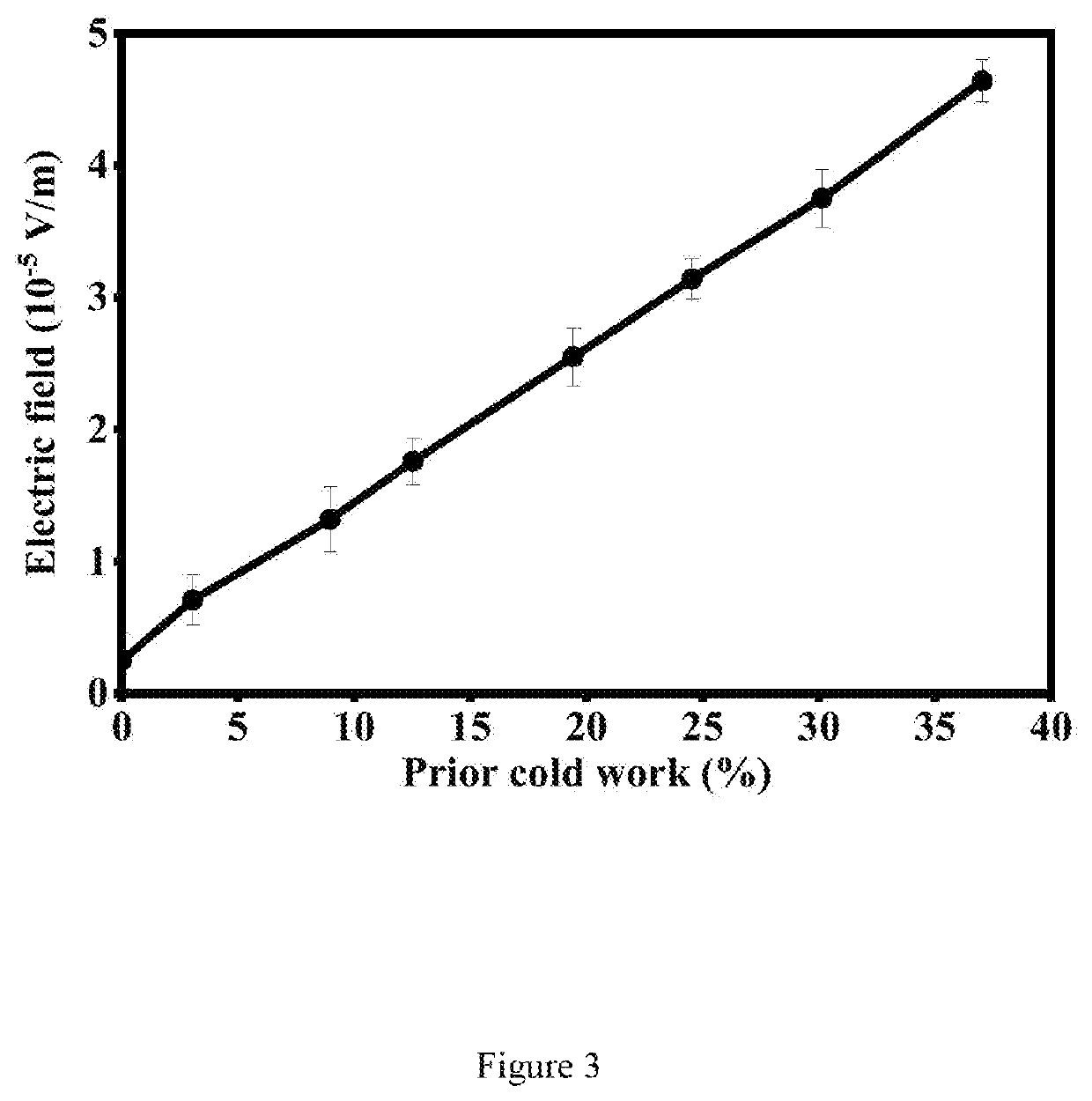
[0115]Mechanical rolling (cold unidirectional rolling) is conducted at room temperature without lubrication, using a conventiona...

example 2

[0118]This example pertains to the effect of stress on the electric dipole for the case of copper as the electrically conductive material in the electret. The copper is the same as the copper foil (without cold work) in Example 1.

[0119]The effect of stress on the electric dipole is a phenomenon that gives an electric output in response to a stress input. The electric output can be the electric field (which relates to the voltage) or the capacitance. An increase in the tensile stress in the elastic regime causes the electric field output to decrease monotonically and reversibly (FIG. 5), such that the fractional decrease in electric field reaches 43% at the maximum stress of 18 MPa. Furthermore, an increase in the tensile stress in the elastic regime causes the capacitance to increase monotonically and reversibly (FIG. 6). Thus, stress sensing can be achieved by measuring the electric field or the capacitance. This means self-sensing, as the copper senses itself.

[0120]In measuring th...

example 3

[0122]This example pertains to the effect of the inter-electrode distance (up to 1280 m) on the electric field for the case of copper (copper wire) as the electrically conductive material in the electret.

[0123]The wire has American wire gauge No. 28, with diameter 0.321 mm (excluding the enamel insulating coating). It is spirally wound. The inter-electrode distance is increased in steps of 8 m (meters) and the enamel coating is removed at the points of the electrodes by using sandpaper prior to the application of silver paint.

[0124]The linearity of the electric field vs. the inter-electrode distance / up to 1280 m is shown in FIG. 7. This indicates that the linearity is maintained even at very large values of l. This behavior is valuable for using large structures as power sources.


PUM

PropertyMeasurementUnit
electric fieldaaaaaaaaaa
electrical conductivityaaaaaaaaaa

Abstract

This invention provides electrically conductive electret, electret-based direct-current power source and structural electret, with applications including the self-sensing of damage, stress and strain (including structural self-sensing) and electric powering (including structural self-powering). The electret is an electrically conductive material comprising mobile charge carriers (electrons, holes or ions), which exhibit a gradient in the carrier concertation along a line connecting the positive charge center and negative charge center in the electret. The carriers create an electric dipole. The material is electrically continuous along this line, which is along the path of least electrical resistance. The material exhibits microstructure comprising microscopic features that are positioned along said line and that interact with said carriers, with the interaction enhancing said dipole. The materials are preferably metals, carbons and their composites. The electret's electric field preferably ranges from 10′ V / m to 1 V / m. The electrical conductivity preferably ranges from 103Ω−1·m−1 to 108Ω−1·m−1.

Description

FIELD OF THE INVENTION[0001]The present disclosure relates to the field of electrets.BACKGROUND OF THE INVENTION[0002]Electric power sources include solar, nuclear, hydroelectric, wind, natural gas, coal, biomass and petroleum. In spite of the large variety of existing power sources, energy remains a significant issue all over the world. Examples of issues include the greenhouse gas emission associated with the burning of fossil fuels, the oil spills associated with offshore oil wells, the fires due to oil / gas leakage from oil / gas pipelines, the environmental pollution associated with the disposal of batteries and supercapacitors, the fire hazard of some batteries and supercapacitors, the inadequate public safety of nuclear reactors, the high cost of photovoltaics (solar cells) in the absence of government subsidies, the cost (and sometimes difficulty and inadequate safety) of transporting the energy from the place of generation of the particular form of energy to the place of energ...

Claims


Application Information

Patent Timeline
Patent Type & Authority Patents(United States)
IPC IPC(8): H01G7/02H02N1/00H01L29/24
CPCH01G7/02H02N1/00H01L29/24H01G7/021H01G7/025H01G7/028Y02T10/70
Inventor CHUNG, DEBORAH DUEN LING
Owner CHUNG DEBORAH DUEN LING
Why Eureka
Try Eureka