Metal film and metal film-coated member, metal oxide film and metal oxide film-coated member , thin film forming apparatus and thin film forming method for producing metal film and metal oxide film

Active Publication Date: 2002-09-12
KYOCERA OPTEC
View PDF4 Cites 26 Cited by
  • Summary
  • Abstract
  • Description
  • Claims
  • Application Information

AI Technical Summary

Benefits of technology

0012] A main object of the present invention is to provide a metal film of high quality single crystal

Problems solved by technology

Meanwhile a metal film such as thin silver film formed by vacuum deposition is extremely vulnerable to the influence of the environment, and is subjected to white clouding caused by an oxide film formed on the surface thereof in about 24 hours when left in the atmosphere as it has been vapor-deposited, and the metal film may be blackened and peel off in the worst case.
Also when the metal film does not sufficiently adhere to the base material, water may infiltrate into the interface with the base material and cause erosion.
However, since the metal films obtained by these methods have rough surfaces with the crystal being poorly oriented, it has been difficult to achieve high reflectivity.
There have also been such problems as the white clouding of the metal film surface due to oxidation and weak bonding with the substrate surface as described previously.
However, since sufficient reaction energy cannot be obtained simply by accelerating oxidation in the case of vacuum deposition process in which chromium oxide is evaporated and deposited in

Method used


Image

  • Metal film and metal film-coated member, metal oxide film and metal oxide film-coated member , thin film forming apparatus and thin film forming method for producing metal film and metal oxide film
  • Metal film and metal film-coated member, metal oxide film and metal oxide film-coated member , thin film forming apparatus and thin film forming method for producing metal film and metal oxide film
  • Metal film and metal film-coated member, metal oxide film and metal oxide film-coated member , thin film forming apparatus and thin film forming method for producing metal film and metal oxide film

Examples


Example

Example 1

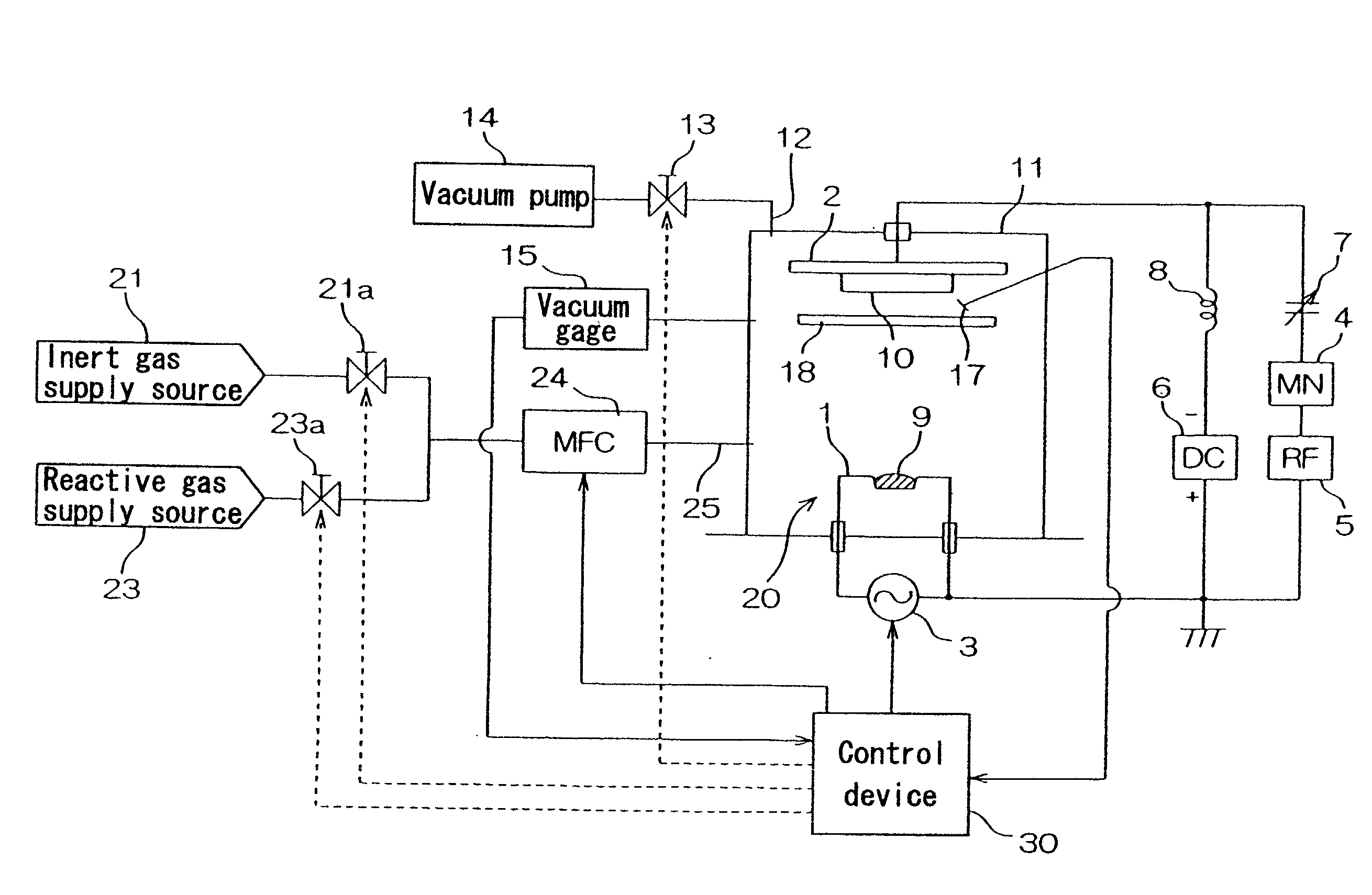
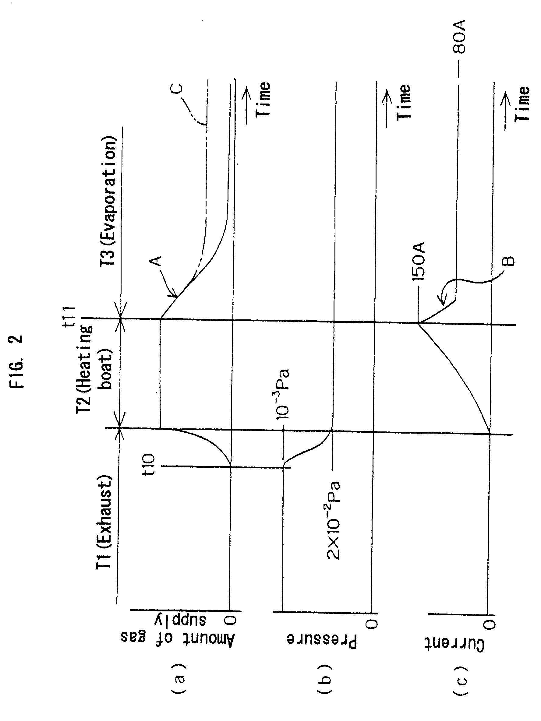
[0202] A silver film was formed in the process shown in FIG. 2 by using the thin film forming apparatus shown in FIG. 1, under the following conditions.

[0203] Substrate 10: A glass sheet 3 mm in thickness.

[0204] Evaporation material 9: Silver.

[0205] Gas introduced into the chamber 11: Argon gas.

[0206] Power supplied from the high frequency power source 5 to the substrate holding section 2: 85 mW / cm.sup.2 (power supplied per unit area of the substrate holding section 2) at frequency 13.56 MHz.

[0207] DC voltage source 6: Cathode connected to the substrate holding section 2 and anode connected to the boat 1.

[0208] Voltage applied by the DC voltage source 6 to the substrate holding section 2: 230 V.

[0209] Chamber 11: Electrically floated without grounding.

[0210] Rate of forming the metal film: 18 .ANG. / second.

[0211] (a) Early stage of forming metal film (period T2 shown in FIG. 2)

[0212] Pressure in the chamber 11: Constant at 2.times.10.sup.-2 Pa.

[0213] Current supplied from th...

Example

Comparative Example 1

[0218] A silver film 1500 .ANG. in thickness was formed on a substrate 53 (glass sheet 3 mm in thickness) with an ordinary ion plating apparatus shown in FIG. 8. This apparatus was arranged so as to form plasma in the vicinity of an antenna 51 connected to a high frequency power supply 50 (output power 400 W at frequency 13.56 MHz). Argon gas was introduced into the chamber 52 of which pressure was set to 2.times.10.sup.-2 Pa. The substrate 53 and the chamber 52 were grounded at the same potential, while a silver film was formed on the surface of the substrate 53 with self-bias setup. Silver that was used as the evaporation material 54 was evaporated by the irradiation of electron beam from an electron gun 55.

Example

Comparative Example 2

[0219] A silver film 1500 .ANG. in thickness was formed on a substrate 63 (glass sheet 3 mm in thickness) with an ordinary vacuum vapor deposition apparatus of resistive heating system shown in FIG. 9. This apparatus was arranged so as to evaporate an evaporation material 64 (silver) by heating with current of 320 A supplied from an AC power source 65 thereby to deposit on a substrate 63 in a chamber 62 of which inner pressure was set to 2.times.10.sup.-2 Pa.

[0220] (Evaluation Test)

[0221] Evaluation tests were conducted on the silver films obtained in Example 1 and Comparative Examples 1, 2.

[0222] 1. Surface Roughness of Silver Film

[0223] Surfaces of the silver films 1500 .ANG. in thickness formed as described above were observed with an atomic force microscope (Nano Scope II manufactured by Digital Instruments Inc.), to take an image of the surface irregularity with an accuracy on the order of nanometers and determine the arithmetic mean surface roughness (Ra)....


PUM

PropertyMeasurementUnit
Angleaaaaaaaaaa
Angleaaaaaaaaaa
Angleaaaaaaaaaa

Abstract

The metal film of the present invention is a dense film of a single crystal that has very low surface roughness and very good crystal orientation because an arithmetic mean roughness of the surface is not larger than 2 nm and a (111) peak intensity of X-ray diffraction is not less than 20 times the sum of all other peaks. Also the metal oxide film of the present invention is a dense film that includes less oxygen defects and almost no voids therein because a content of a non-oxidized metal is not higher than 1 mole % of a metal component that constitutes the metal oxide and a packing density is 0.98 or higher.

Description

FIELD OF THE INVENTION[0001] The present invention relates to a metal film and a metal film-coated member used for optical coating film or the like, a metal oxide film and a metal oxide film-coated member used for optical coating film, insulation film or the like, and a thin film forming apparatus and a thin film forming method preferably employed in the production of the metal film and the metal oxide film.BACKGROUND OF THE INVENTION[0002] Coating of various substrates with metal films has been employed for such applications as decoration, improvement of electric characteristics and optical functions. Such metal films are employed for making use of intrinsic physical properties of the metals such as luster, shade, electric properties and optical properties in accordance to the application, while it is desired that the physical properties remain stable for a long period of time.[0003] In the case of metal films used in optical applications including reflector mirror such as those re...

Claims


Application Information

Patent Timeline
IPC IPC(8): C23C14/00C23C14/08C23C14/10C23C14/14C23C14/32C30B23/02G02B1/10G21K1/06
CPCC23C14/0021C30B29/02C23C14/08C23C14/081C23C14/083C23C14/10C23C14/14C23C14/32C30B23/02G02B5/0858G21K1/06G21K2201/06Y10T428/31678Y10T428/12993Y10T428/12736Y10T428/12896Y10T428/12174C23C14/0694
Inventor OKURA, TAKAHIROSHIMIZU, KAZUYATAKEI, MASAKAZU
Owner KYOCERA OPTEC
Why Eureka
Try Eureka