Manufacturing method of organic electroluminescent element

a manufacturing method and electroluminescent element technology, applied in the field of manufacturing methods of organic electroluminescent elements, can solve the problems of remarkable luminance degradation, difficult heat treatment of substrates having transparent electrodes at a temperature of 200.degree, and deterioration of organic el elements

Inactive Publication Date: 2003-11-13
PIONEER CORP
View PDF10 Cites 5 Cited by
  • Summary
  • Abstract
  • Description
  • Claims
  • Application Information

AI Technical Summary

Problems solved by technology

This causes a problem of deteriorating the characteristics of the organic EL element such as light emission luminance and insulation.
However, since a substrate portion of the substrate having a transparent electrode is preferably made of synthetic resin with good moldablity and the synthetic resin generally has a limit of heat resistance of about 200.degree. C., it is difficult to heat-treat such the substrate having a transparent electrode at a temperature of 200.degree. C. or higher.
The heat treatment at a low temperature of about 200.degree. C. leads to remarkable deterioration of the luminance

Method used


Image

  • Manufacturing method of organic electroluminescent element
  • Manufacturing method of organic electroluminescent element
  • Manufacturing method of organic electroluminescent element

Examples


first embodiment

[0025] this invention will be described with reference to accompanying drawings.

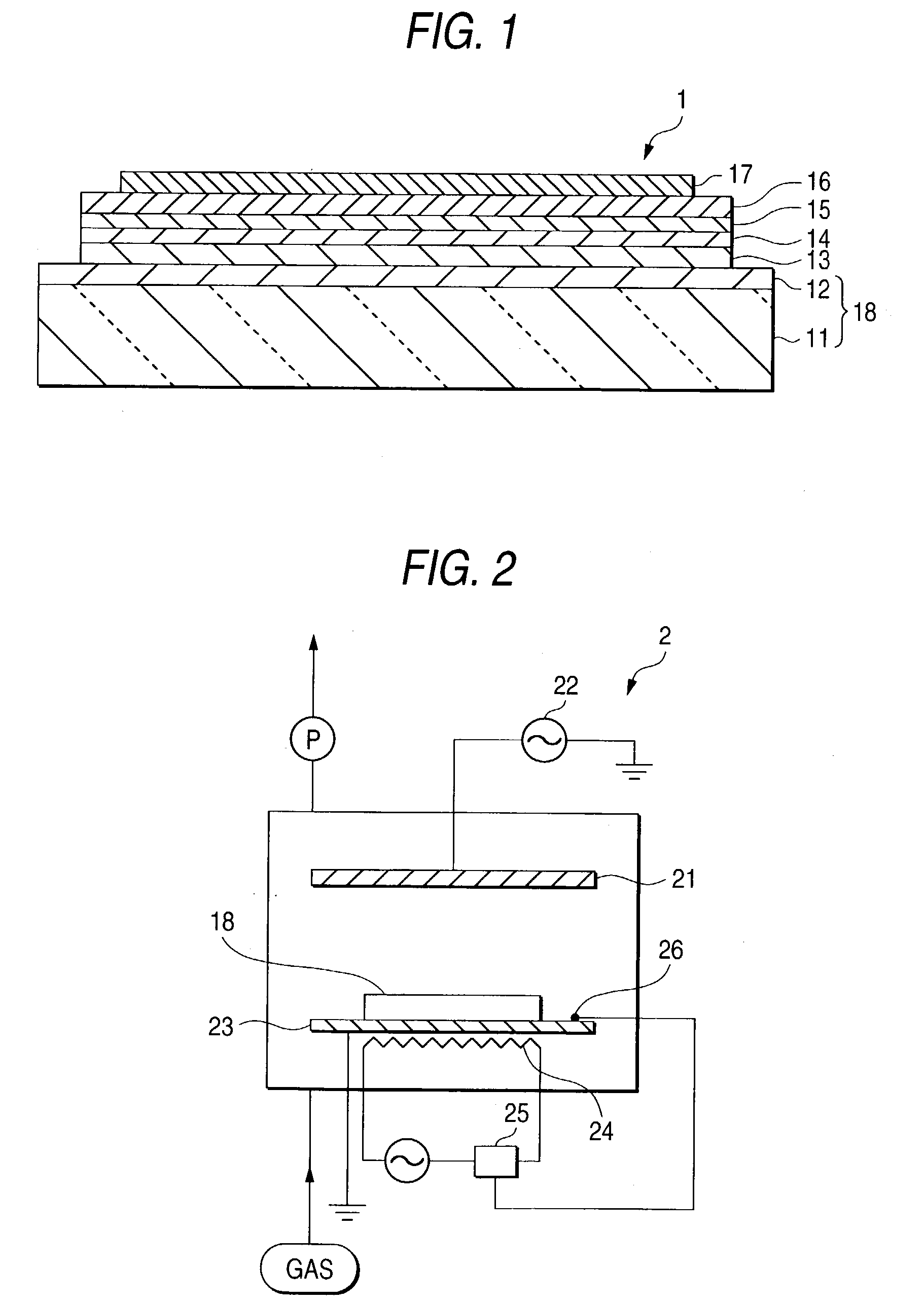
[0026] FIG. 1 shows an organic EL element 1 according to this embodiment. The organic EL element 1 includes a substrate portion 11, a transparent electrode (anode) 12 of an IZO film disposed on the substrate portion 11, a hole injecting layer 13 that is an organic layer deposited on the transparent electrode 12, a hole transporting layer 14 that is an organic layer deposited on the hole injecting layer 13, a light emitting layer 15 that is an organic layer deposited on the hole transporting layer 14, an electron injecting layer 16 deposited on the light emitting layer 15 and an electrode (cathode) 17 deposited on the electron injecting layer 16.

[0027] The substrate portion 11 is made of synthetic resin such as polycarbonate.

[0028] The hole transporting layer 14 is made of aromatic amine derivative such as N,N'-diphenyl-N,N'-(3-methylphenyl) -1,1'-bisphenyl-4,4'-diamine.

[0029] The light emitting layer 15 ...

example

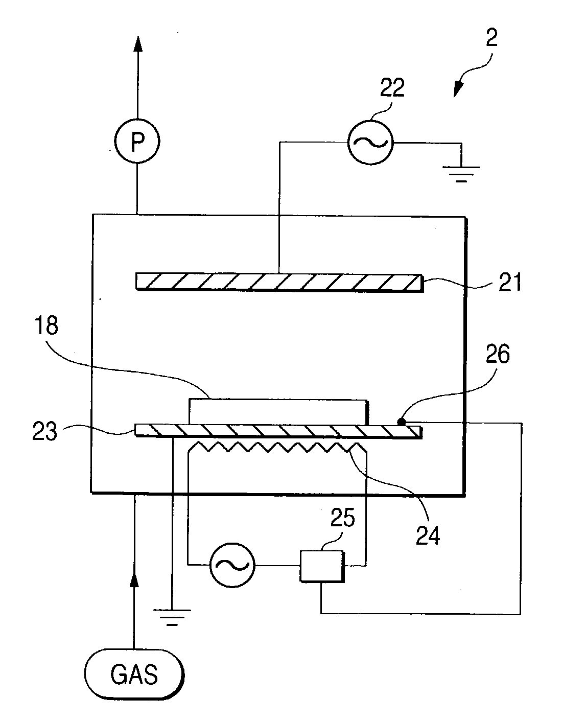
[0057] Using the plasma generating apparatus 2 employed in the embodiments described above, organic EL elements having the same structure as in the embodiments described above was manufactured. Two kinds of organic EL elements with the transparent electrodes of ITO and IZO were manufactured.

[0058] The plasma treatment was carried out within an atmosphere of a mixed gas of carbon tetrafluoride and oxygen (oxygen density of 5%) under the conditions of a temperature of the electrode-equipped substrate of 50.degree. C., a high frequency of 13.56 MHz and pressure of 0.9 Torr (120Pa). The flow rate of the mixed gas was 200SCCM (the gas flow rate calibrated at 0.degree. C. and 1 atom is 200 cc / min), the RF power was 50 mW / cm.sup.2, and the treatment time was 10 minutes.

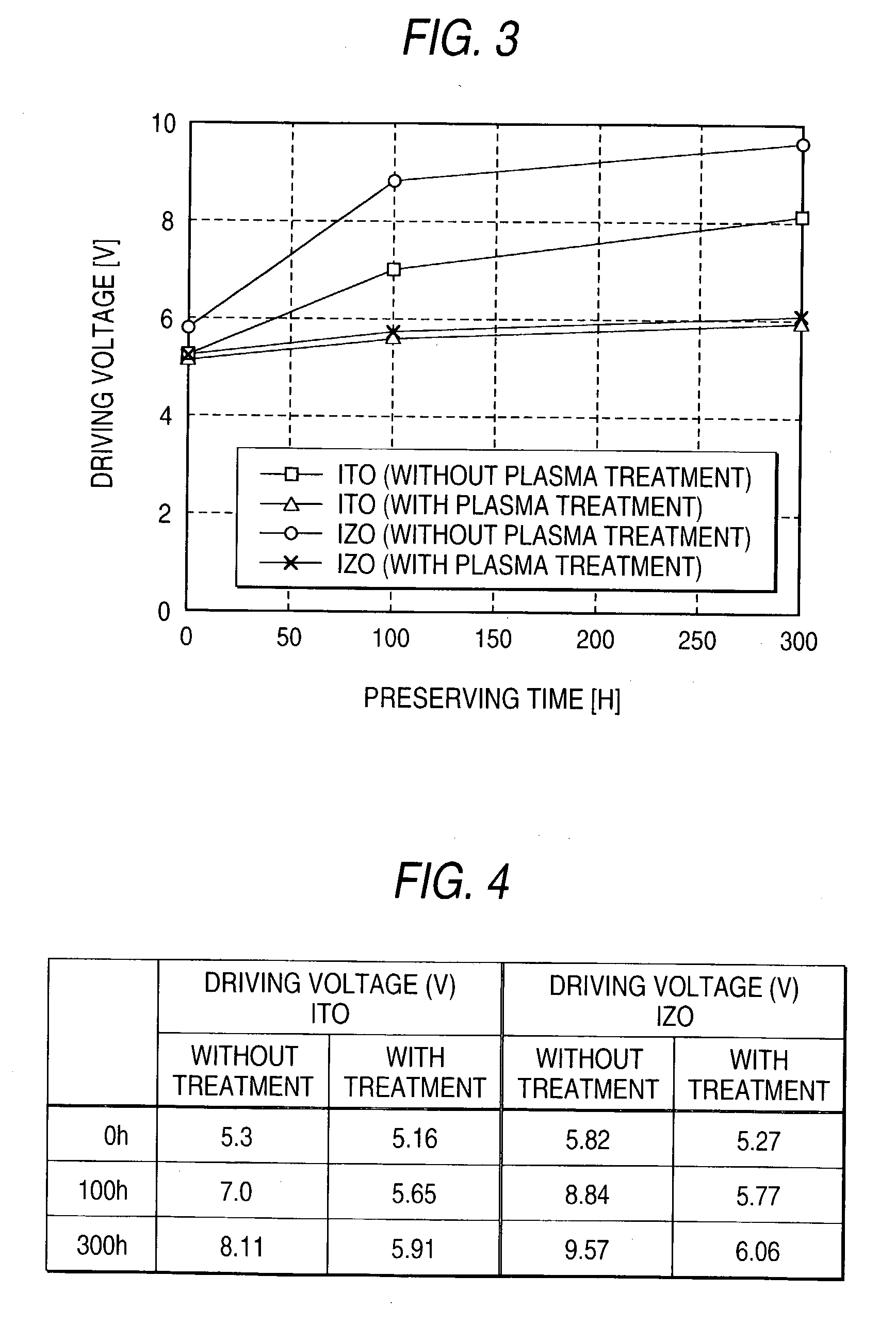
[0059] After the organic EL elements thus manufactured were placed in an oven maintained at 100.degree. C., changes in the driving voltage with respect to 100.degree. C. preserving time were observed with the current density...


PUM


Abstract

An electrode-equipped substrate includes a substrate portion of synthetic resin and a transparent electrode. The electrode-equipped substrate is subjected to heat treatment at a temperature of 200° C. or less as well as plasma treatment before organic layers are deposited. The plasma treatment is carried out within atmosphere of (A) a mixed gas of oxygen and any one of nitrogen, argon, helium, neon and xenon, with an oxygen density of 5% or less; (B) a mixed gas of oxygen and any one of carbon tetrafluoride, hexafluoroethane, octafluoropropane and octafluorocyclobutane; or (C) a sole gas of nitrogen, argon, helium, neon, xenon, carbon monoxide, carbon dioxide, nitrogen monoxide or nitrous oxide.

Description

[0001] The present disclosure relates to the subject matter contained in Japanese Patent Application No. 2002-63570 filed Mar. 8, 2002, which is incorporated herein by reference in its entirety.[0002] 1. Field of the Invention[0003] This invention relates to a manufacturing method of an organic electroluminescent (EL) element.[0004] 2. Description of the Related Art[0005] Conventionally, the organic electroluminescent element (organic EL element) has a structure in which organic layers such as a light emitting layer and a cathode are stacked on a substrate having a transparent electrode. These layers are formed on the substrate having a transparent electrode by vacuum evaporation or sputtering.[0006] In manufacturing such the organic EL element, in order to prevent the light-emission luminance of the organic EL element from deteriorating, the substrate having a transparent electrode is subjected to a pretreatment before the organic layers are deposited. The pretreatment for the subs...

Claims


Application Information

Patent Timeline
IPC IPC(8): H01L27/32H01L51/50H05H1/46H01L51/52H05B33/02H05B33/10
CPCH01L51/5206H01L27/3295H10K59/173H10K50/81H10K2102/311
Inventor KUBOTA, HIROFUMIYOSHIZAWA, TATSUYAMIYAKE, TAKAKO
Owner PIONEER CORP
Why Eureka
Try Eureka