However, fuel cells typically operate only with
hydrogen as the fuel.
Prior art fuel cells utilizing
hydrocarbon fuels directly have encountered significant problems.
For example, direct-
methanol polymer electrolyte fuel cells produce relatively low power densities and require prohibitively large Pt loading of the anodes.
Furthermore, only
alcohol fuels appear feasible with this approach.
However, maintaining appropriate
gas composition and temperature gradients across a large area SOFC stack is challenging.
For instance, if the reforming reactions are slow, then insufficient H.sub.2 is supplied to the SOFCs.
On the other hand, fast reforming reactions cause cooling localized near the fuel inlet, leading to poor
cell performance, and possible
cell fracture.
However, prior art attempts with SOFCs operating at temperatures T.sub.c=900-1000.degree. C. with
methane fuel have been less than satisfactory: either power densities were very low or
carbon deposition was observed.
However, such systems have not been considered or used for direct-
hydrocarbon operation, because
carbon deposition reaction rates decrease with decreasing temperature.
Tubular stacks avoid sealing and manifolding problems inherent to planar stacks, but take a large volume for a given
cell active area and can show significant ohmic losses related to current transport around the tube circumference through the (La,Sr)MnO3 (LSM)
cathode.
Another problem is the relatively poor mechanical
toughness of LSM.
Alternatively, planar stacks can provide
higher power-to-volume ratios than tubular stacks, but are not as mechanically robust as tubes and require excellent seals.
Another problem with many planar stack designs is that they require pressure contacts between separate SOFC and interconnect plates.
This places stringent requirements on the flatness of large-area
ceramic plates, making manufacturing difficult and expensive.
Furthermore, there are often relatively high resistances associated with these contacts, which deleteriously affect stack performance.
Even so, the disadvantages associated with each respective approach present obstacles for effective use of SOFCs and suggest a new direction is needed to better utilize and benefit from this technology.
There are a considerable number of problems and the deficiencies associated with the use of hydrocarbons with
solid oxide fuel cells.
Indeed, this may be the only feasible approach for low-temperature SOFCs, since extrapolation of internal reforming rate data below 750.degree. C. suggests that reforming rates become prohibitively small.
Consistent with the foregoing and various data provided herein, as supported by electrical / cell models,
electrode /
cathode sheet resistance can limit performance due to low measured conductivities.
1. Improved
mechanical strength and
toughness. The devices are deposited onto an electrically insulating
ceramic that can be chosen for desired strength,
toughness,
thermal conductivity, and
thermal expansion match to cell components. Partially-stabilized zirconia is a preferred choice based on, its high toughness [T. Yoshida, T. Hoshina, I. Mukaizawa, and S. Sakurada, J. Electrochemical Society, 146, 2604 (1989)] and good
thermal expansion match. Other materials with lower electrical
conductivity and higher
thermal conductivity may also be advantageous.
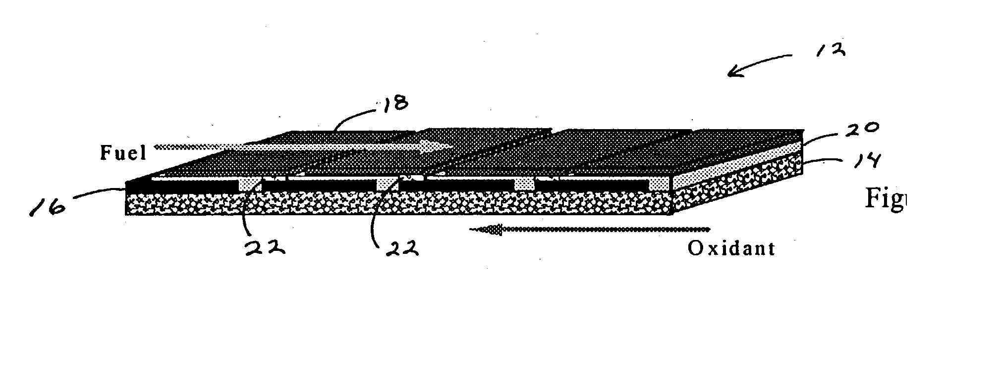
2. Simplified gas manifolding and sealing. The stacking geometry shown in FIG. 1 would require seals like other planar stacks. However, a flattened tube design allows simple gas manifolding as in various tubular stacks of the prior art.[S. C. Singhal, Proc. 6th Intl. Symp.
Solid Oxide Fuel Cells, Ed. By S. C. Singhal and M. Dokiya (Electrochemical Society, Pennington, N.J., 1999.] That is, one gas is introduced through a feed tube into the closed-end flattened tube, and the other is fed to the outside. No sealing is required, or a single seal at the tube end can be used.
3. Small volume and weight. The design eliminates the separate interconnect pieces present in most planar stacks, and at the same time reduces the number of gas-flow channels by a factor of two. These changes reduce the volume and weight required to generate a given amount of power.
4. Reduced internal electrical losses. The integrated stack features intimate contact of electrodes with interconnects, eliminating the resistance loss associated with the pressure contacts used in many planar stacks.[B. Krogh, M. Brustad, M. Dahle, J. L. Eilertsen, and R. Edegard, Proceedings of the 5th International Symposium on
Solid Oxide Fuel Cells, Ed. By U.Stimming, S. C. Singhal, H. Tagawa, and W. Lehnert, (Electrochemical Society, Pennington, 1997) p. While pressure contacts to both ends of the integrated stack elements are required for current collection, the
subdivision of the cell area into a large number of small series-connected cells results in relatively low currents and high voltages, such that losses at these contacts are minimal. Compare, for example, a 10 cm.times.10 cm single cell with the same size integrated stack element. Assuming a single cell producing 0.5 W / cm.sup.2 at an
operating voltage of 0.7V, the
total current is 70A. On the other hand, the same area integrated stack with 45 2-mm-wide cells and 0.2-mm-wide interconnects will run at 22.5 V and .apprxeq.2A. Assuming 2-mm-wide
current collector strips at either end of the integrated stack, the collector
current density would be the same as for a conventional cell. Thus, an .apprxeq.1 .
OMEGA.cm.sup.2
contact resistance would yield .apprxeq.0.5V drop at the contact: this would roughly halve the
power density from the single cell, but would have negligible effect on the integrated stack.
A major difficulty was obtaining patterned deposits with methods such as thick-film
slurry coating and electrochemical vapor deposition (EVD).
Disadvantages of these methods include the difficulty in scaling them into reliable
mass production steps, the poor spatial resolution that led to relatively large unit cell sizes (1 cm), and the
cycling to high temperature (.apprxeq.1500.degree. C.) required for each deposition step.

