NOx, Hg, AND SO2 REMOVAL USING AMMONIA

Inactive Publication Date: 2004-06-03
POWERSPAN CORP
View PDF47 Cites 24 Cited by
  • Summary
  • Abstract
  • Description
  • Claims
  • Application Information

AI Technical Summary

Benefits of technology

0025] Although FIG. 1 shows ammonia being added at this step, ammonia in the form of ammonium hydroxide can be added instead. The ammonia reacts with the gas stream output from the oxidizing step, forming ammonium sulfite and ammonium bisulfite. The likely chemical reactions in this step are as follows:
0026] An oxidation inhibitor can be added at this step to inhibit the oxidation of sulfite to sulfate before the sulfite can perform its NO.sub.2 reduction function. Examples of oxidation inhibitors include thiosulfate and thiourea.
0027] The ammonium bisulfite and ammonium sulfite reacts with the NO and N0.sub.2 to form ammonium sulfate. Ammonium sulfate is well known as a valuable agricultural fertilizer. The likely reactions that take place in this step are as follows:
0028] Most of the HNO.sub.3 that may have been formed by further oxidation of NO and NO.sub.2, and/or created by a DBD reactor, will react with ammonia and form ammonium nitrate, also k

Problems solved by technology

These byproducts are known to have serious negative health effects on people, animals, and plants, and a great deal of research has been done to find a way to economically remove them from flue gas streams before they enter the atmosphere.
The process does not remove NO or NO.sub.2, however, which must then be dealt with using a different process.
This process, however, does not remove SO.sub.2, and requires the addition of chlorine or o

Method used


Image

  • NOx, Hg, AND SO2 REMOVAL USING AMMONIA
  • NOx, Hg, AND SO2 REMOVAL USING AMMONIA
  • NOx, Hg, AND SO2 REMOVAL USING AMMONIA

Examples


example 2

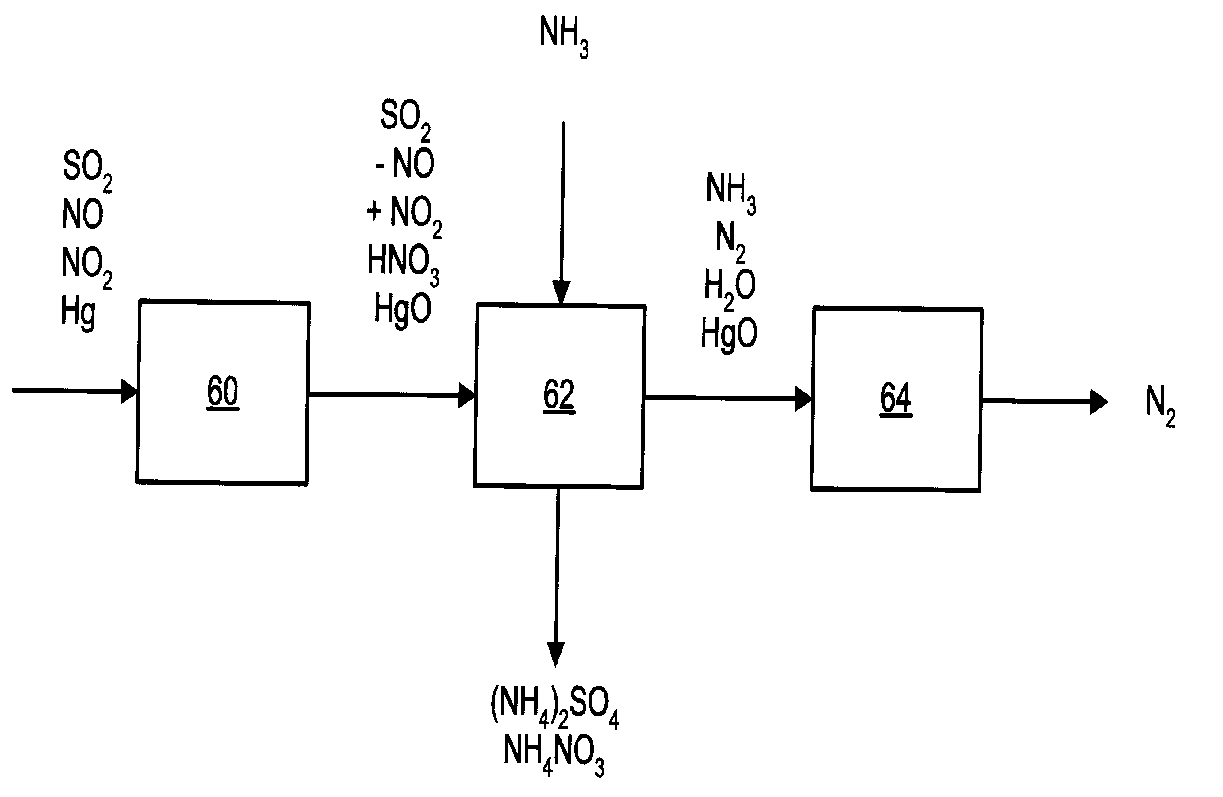
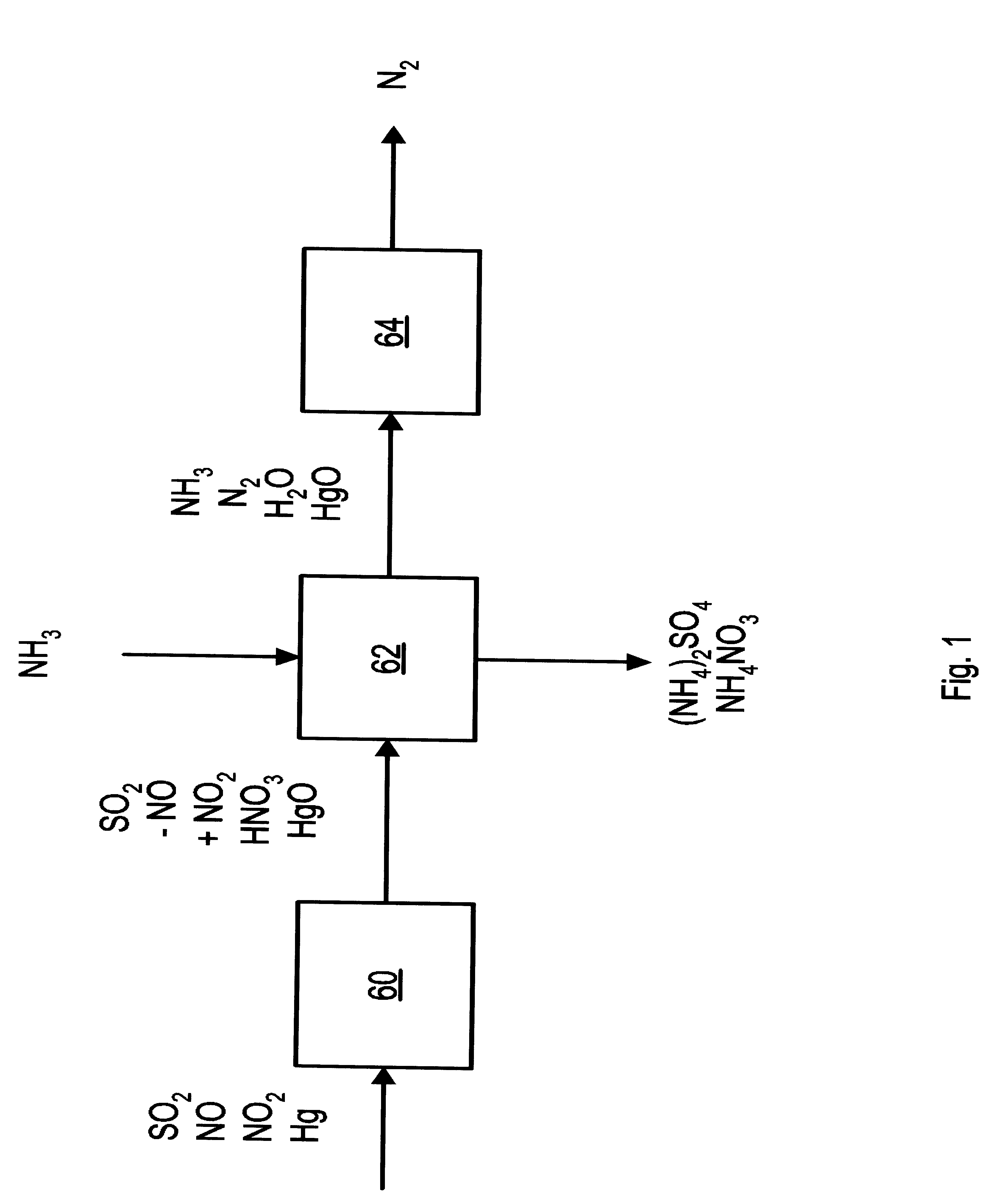
[0042] An absorption test was done for the scrubbing step of the process of the present invention starting with water and a flue gas stream consisting of 13% v / v moisture, 17 ppmv NO, 267 ppmv NO.sub.2, 1360 ppmv SO.sub.2, 6% v / v O.sub.2 and balance N.sub.2. Ammonia and ammonium thiosulfate were added to maintain a pH of 6.8 and a thiosulfate concentration of 2.5%, and the concentrations of sulfite and sulfate in the system were allowed to build to steady state. The NOx removal rate was 80% w / w at concentrations of SO.sub.3.sup.2-, SO.sub.4.sup.2-and S.sub.2O3.sup.2-of 0.7% w / w, 2.5% w / w, and 0.5% w / w respectively.

example 3

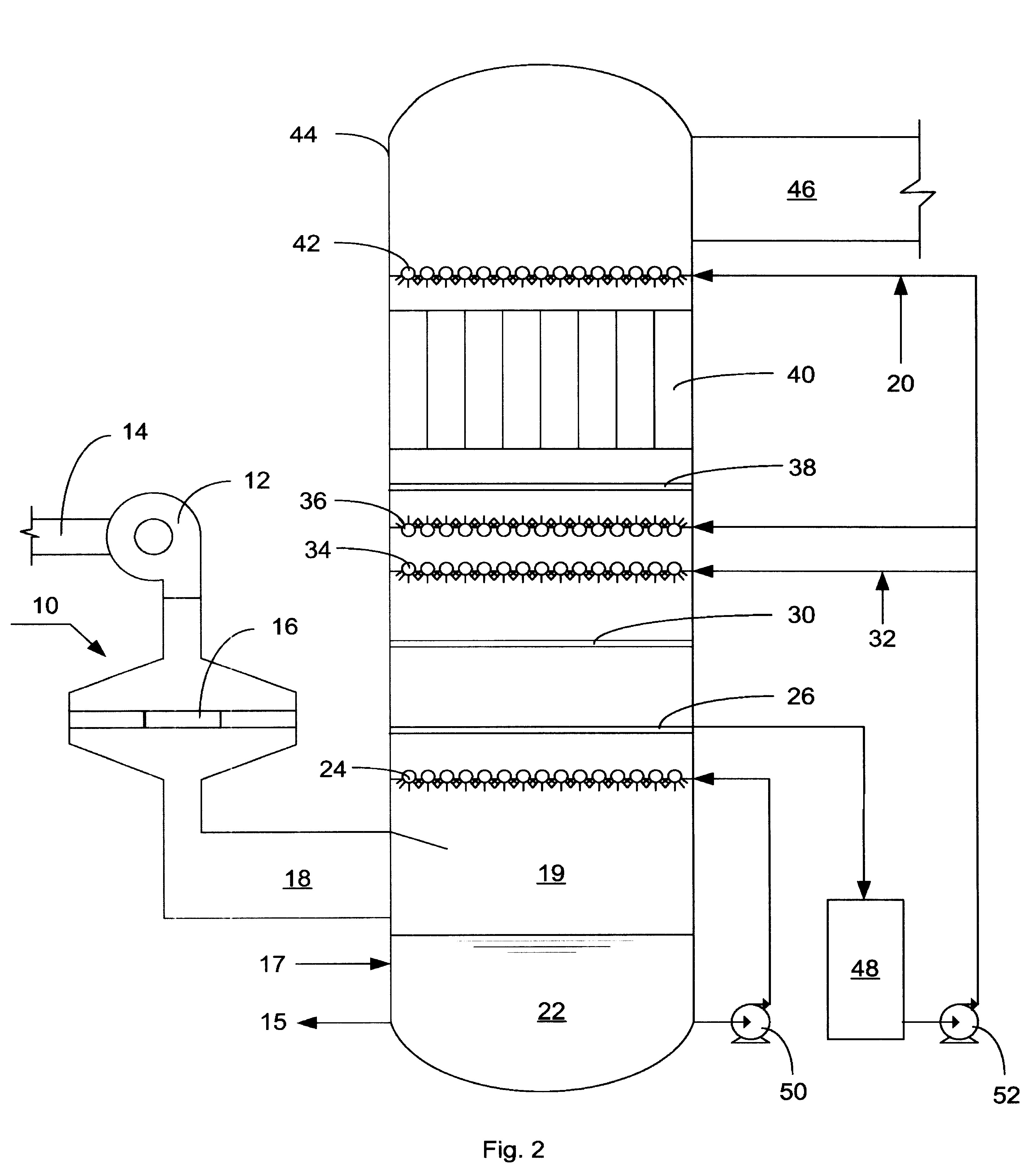
[0043] Tests were conducted in a laboratory test facility for the NO oxidizing, scrubbing, and aerosol removal steps of the process of the present invention. The equipment consisted of a simulated flue gas delivery system, a coaxial cylinder DBD reactor, a packed column scrubber and a tubular WESP. The following is an example of data obtained in the lab test facility.

[0044] Simulated flue gas was delivered to the DBD reactor at a flow rate of 14 scfm, a temperature of 290.degree. F. and with the following composition: 6.2% v / v O.sub.2, 14.2% v / v CO.sub.2, 8.2% v / v H.sub.2O, 20 ppmv CO, 250 ppmv C.sub.2H.sub.4, 1740 ppmv SO.sub.2, and 259 ppmv NO.sub.x. Gas velocity through the discharge reactor was 50 ft / sec with discharge power level of 140 watts.

[0045] Gas from the discharge reactor entered a 4" ID packed column scrubber, packed with 1 / 2" INTALOX saddles to a depth of 4 feet. Liquid was introduced at the top of the scrubber at a flow rate of 0.33 gpm (L / G=20 gpm / kacfm). Aqueous am...


PUM


Abstract

A process and apparatus for removing S02, NO, and N02 from a gas stream having the steps of oxidizing a portion of the NO in the flue gas stream to N02, scrubbing the S02, NO, and N02 with an ammonia scrubbing solution, and removing any ammonia aerosols generated by the scrubbing in a wet electrostatic precipitator. The process can also remove Hg by oxidizing it to HgO and removing it in the wet electrostatic precipitator. Ammonium sulfate, a valuable fertilizer, can be withdrawn from the scrubbing solution.

Description

BACKGROUND OF INVENTION[0001] 1. a. Field of the Invention.[0002] This invention relates to methods and apparatuses for removing NOx and SO.sub.2 from a gas stream.[0003] 2. b. Description of the Related Art.[0004] Fossil fuels are burned in many industrial processes. Electric power producers, for example, burn large quantities of coal, oil, and natural gas. Sulfur dioxide ("SO.sub.2"), nitrogen oxide ("NO"), and nitrogen dioxide ("N.sub.O.sup.2") are some of the unwanted byproducts of burning any type of fossil fuel. Mercury ("Hg") is often also found in fossil fuels. These byproducts are known to have serious negative health effects on people, animals, and plants, and a great deal of research has been done to find a way to economically remove them from flue gas streams before they enter the atmosphere.[0005] SO.sub.2 is often removed from gas streams ("desulfurization") by scrubbing the gas with an aqueous ammonium sulfate solution containing ammonia. Examples of this process are ...

Claims


Application Information

Patent Timeline
IPC IPC(8): B01D53/32B01D53/73B03C3/01B03C3/013B03C3/016B03C3/017B03C3/16C01B17/74C01B21/38C01G13/02F01N3/01F23J15/00F23J15/02
CPCB01D53/32Y02T10/20B01D2257/302B01D2257/404B01D2257/602B03C3/01B03C3/013B03C3/016B03C3/017B03C3/16C01B17/74C01B21/38C01G13/02F01N3/01F23J15/006F23J15/025F23J2215/10F23J2215/20F23J2215/60F23J2217/102F23J2217/40F23J2217/60B01D53/73Y02A50/20Y02T10/12
Inventor DUNCAN, JOANNA L.MCLARNON, CHRISTOPHER R.ALIX, FRANCIS R.
Owner POWERSPAN CORP
Why Eureka
Try Eureka