Constant current electroporation device and methods of use

a constant current electroporation and electroporation device technology, applied in the field of constant current electroporation, can solve the problems of inability to reseal the electropore, limited application of plasmid transfer technology in living organisms, and inability to use electroporation, so as to facilitate the introduction of a macromolecule into cells, eliminate cross-contamination, and increase the electroporation efficiency

Active Publication Date: 2005-03-10
INOVIO PHARMA
View PDF76 Cites 397 Cited by
  • Summary
  • Abstract
  • Description
  • Claims
  • Application Information

AI Technical Summary

Benefits of technology

The electroporation device and the EKD can be used to electroporate cells and deliver plasmid DNA without causing permanent damage to adjacent cells. Furthermore, use of the electroporation device causes an increase in electroporation efficiency, meaning that a smaller amount of plasmid is needed to generate adequate levels of target proteins.
The electro-kinetic device (“EKD”) provides a constant-current electric field through the electrode needle array in various user-programmable pulse patterns and facilitates the introduction of a macromolecule into cells of a selected tissue in a body or plant. The EKD comprises an electrode assembly having a plurality of needle electrodes; a current waveform generator for applying a pattern of constant-current pulses or a current pulse train waveform that runs through the electrode array; a power source; a controller for controlling the operation of the current waveform generator and other peripheral devices; and a waveform logger for recording the electroporation voltage and current waveforms that are generated. The controller of the EKD operates through a software or firmware application which enables users to input desired parameters and control the operation of the EKD. The EKD may also include an impedance tester for optional monitoring of the amount of resistance in the target tissue. Other components of the EKD may include: an input device for inputting operating parameters; a status-reporting device for reporting status information; a communications port; memory; and a power switch. Another aspect of the EKD is the electrode assembly, which preferably includes a non-conductive handle. The electrode handle assembly contains the needle electrode array and may contain a status-reporting device and an activation switch. The handle assembly may also be adapted to receive the replaceable electrode disk.
The central channel, or port, of the electrode disk allows the user to inject the medicinal solution and electroporate the tissue area in one operation, which ensures that the injection area will be delineated by the needle electrodes. The electrode disk also el

Problems solved by technology

Plasmid transfer technology has traditionally been limited in scope because in vivo expression levels resulting from the naked DNA transfer have been low, only fractions of that achieved by viral gene transfer.
However, the use of electroporation in living organisms has several problems, including cell death that results from generated heat and the inability of electropores to reseal.
The beneficial effects of the drug or macromolecule are extremely limited with prior art electroporation methods where excessive cell heating and cell death occurs.
Certainly, the difference in upper limit amplitudes of a voltage pulse between electroporation protocols that facilitate effective electroporation and electroporation protocols that cause the cells to die are very small.
Thus, the over heating of cells between across electrodes serves as a principal cause for the ineffectiveness of any given electroporation voltage pulsing protocol.
However, this electrotransfer is associated with significant muscle damage that may result in substantial loss of transfected muscle fibers (McMahon et al., 2001).
The reduction of the voltage used in the technique can result in a decrease in muscle damage, with a concomitant reduction in expression, but without a significant decrease in the number of transfected fibers.
The effectiveness of electroporation is limited by the fact that there is a threshold value for the pulse intensity below which electroporation does not occur, and an upper limit above which the cells are destroye

Method used


Image

  • Constant current electroporation device and methods of use
  • Constant current electroporation device and methods of use
  • Constant current electroporation device and methods of use

Examples


example 1

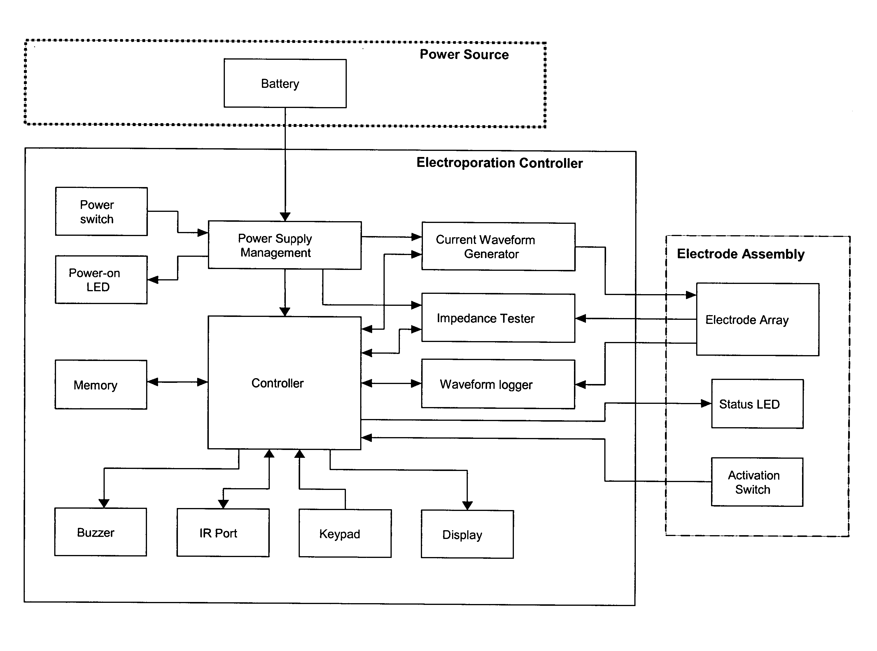
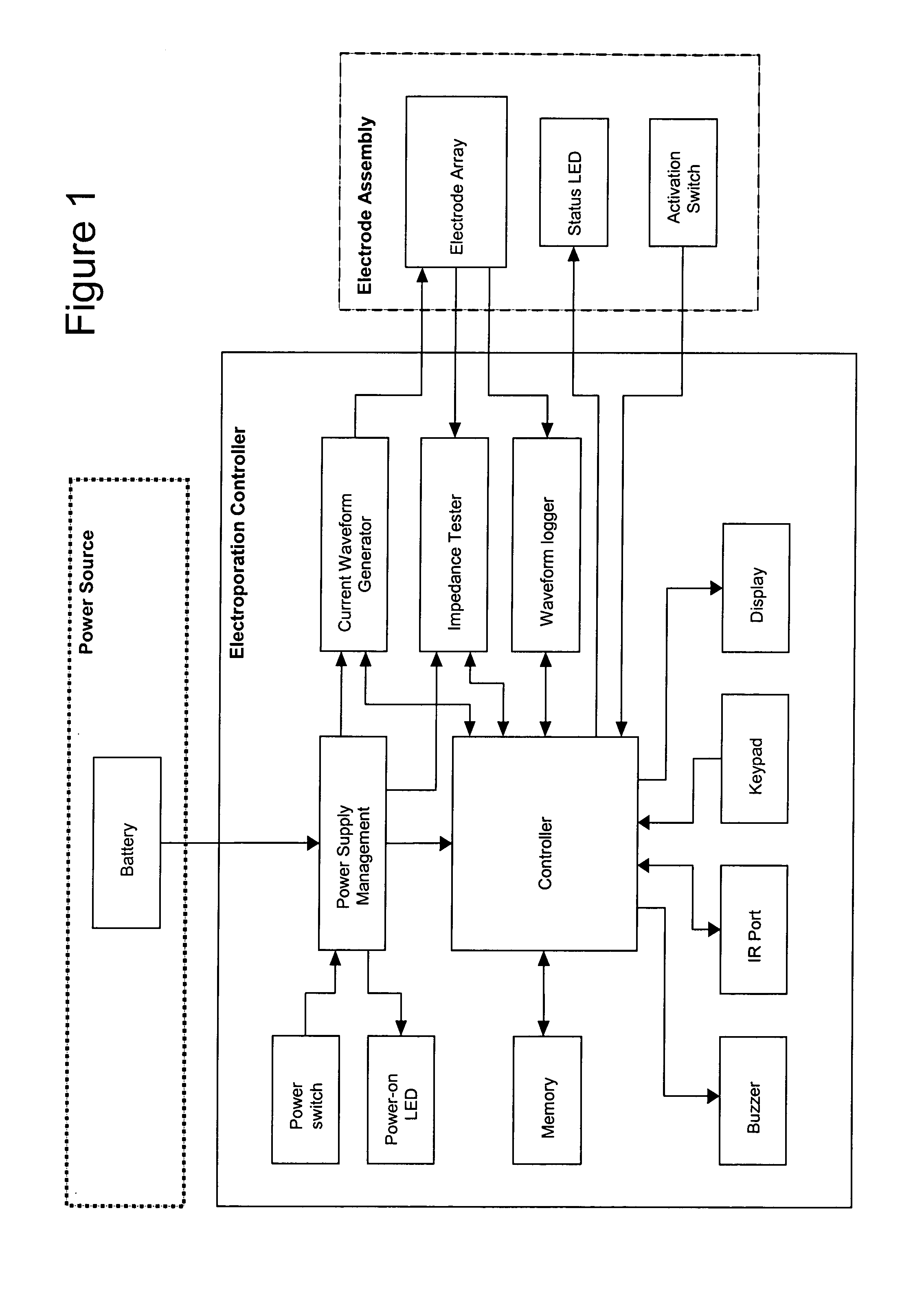
Operation of the Electro-Kinetic Device (“EKD”)

The operation of the Controller is shown in FIGS. 19 and 20, which illustrate a preferred operation sequence of the EKD. In a preferred embodiment, an information display panel LCD displays each step of the sequence to promote user-friendly operation. Prior to operating the EKD, the electrode assembly is firmly inserted into the target tissue.

First, the power is turned on and the EKD is booted up. The firmware remains in the idle state until input is received from the user. To start an electroporation sequence, a password is entered to obtain an introductory prompt on the LCD. At this point, the handle assembly activator switch is pressed. The user then enters a number, preferably an animal ID number, which is logged with the data of every pulse stored for later download. The number is preferably entered using a numeric keypad. The user is then prompted, via a “beep” from the buzzer, to press the activation switch to continue the el...

example 2

Data Acquisition and Storage

The EKD software or firmware enables real time data acquisition and storage in non-volatile memory. FIG. 21 illustrates a first portion of data that may be collected during the electroporation process. The first section of the file header contains the file name and the animal number. The columnar data describes the pulse in sequence, the wait time before pulsing, the pulse width, and the pulse current for each of the five electrodes. FIG. 22 illustrates a second portion of data, which identifies the configuration of each electrode during a given pulse sequence. Reading vertically for the first pulse, electrode 1 is positive, 2 is off, 3 is negative, 4 is negative, and 5 is off. The electrode configurations for pulses 2, 3, 4, and 5 constitute the remainder of the data columns. FIG. 23 illustrates a formatted version of a third portion of raw data for the same electroporation, which consists of 10 time points, about 20 ms apart, for the five electrodes. ...

example 3

Plasmid Design, Delivery Methods, and Experimental Animals

Plasmid construction. The plasmid pSP-SEAP (5019 bp) is a muscle specific expression plasmid for secreted embryonic alkaline phosphatase (“SEAP”). The promoter is SPc5-12, a strong, muscle specific, synthetic promoter (Li et al., 1999), and the 3′ ends of SEAP transcripts are defined by the SV40 late poly(A) signal. The plasmid was constructed by inserting a 394 bp Acc65I-HindIII fragment, containing the 334 bp SPc5-12 promoter sequence, between the Acc65I and HindIII sites of pSEAP-2 Basic Vector (Clontech Laboratories, Inc., Palo Alto, Calif.).

Electroporation conditions. Square wave pulses were used in all experiments. Electroporation conditions are stated individually for each experiment. In all cases, constant current was used at 0.4 to 1.0 Amps, with 3 or 5 pulses, for 52 milliseconds / pulse, and with one second between pulses. The EKD electroporation device contained a circular array (1 cm diameter) of five equally s...


PUM


Abstract

An electroporation device which may be used to effectively facilitate the introduction of a macromolecule into cells of a selected tissue in a body or plant. The electroporation device comprises an electro-kinetic device (“EKD”) whose operation is specified by software or firmware. The EKD produces a series of programmable constant-current pulse patterns between electrodes in an array based on user control and input of the pulse parameters and allows the storage and acquisition of current waveform data. The electroporation device also comprises a replaceable electrode disk having an array of needle electrodes, a central injection channel for an injection needle, and a removable guide disk.

Description

BACKGROUND The present invention relates to an electroporation device and its use for facilitating the introduction of a macromolecule into cells of a selected tissue in a body or plant. The electroporation device comprises an electro-kinetic device (“EKD”) which provides a series of programmable constant-current pulse patterns between electrodes in an array, user control and input of the pulse parameters, and storage and acquisition of data. The electroporation device also comprises a replaceable, or exchangeable, electrode disk having an array of needle electrodes, a central injection channel for an injection needle, and a removable guide disk. Plasmid transfer technology has traditionally been limited in scope because in vivo expression levels resulting from the naked DNA transfer have been low, only fractions of that achieved by viral gene transfer. Numerous investigators have outlined the safety and toxicological concerns with injecting viruses as DNA vectors into animals and...

Claims


Application Information

Patent Timeline
IPC IPC(8): A61N1/30A61N1/32
CPCA61N1/0412A61N1/327A61N1/0476
Inventor SMITH, LOUIS C.DRAGHIA-AKLI, RUXANDRAKHAN, AMIR S.CARPENTER, ROBERT H.DARNELL, JEFF
Owner INOVIO PHARMA
Why Eureka
Try Eureka