

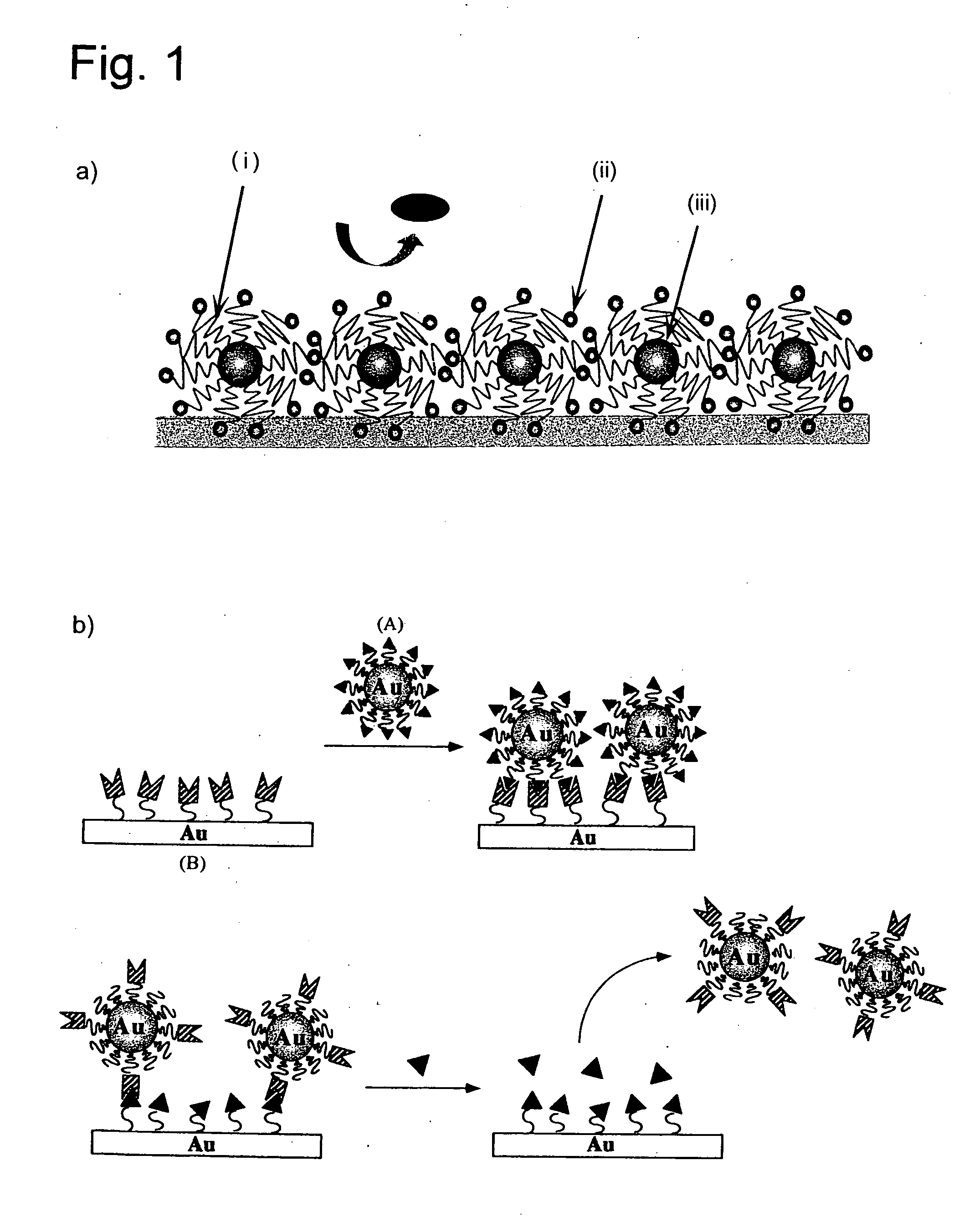
Biochip sensor surface carrying polyethylene glycolated nanoparticles
a biosensor and nanoparticle technology, applied in the field of bioassays, can solve the problems of reduced system sensitivity and inability to prevent non-specific adsorption of impurities, and achieve the effects of increasing bioassay sensitivity, preventing or controlling non-specific adsorption of impurities, and improving dispersion stability in aqueous media
- Summary
- Abstract
- Description
- Claims
- Application Information
AI Technical Summary
Benefits of technology
Problems solved by technology
Method used
Image

Examples
production example 2
[0081] Preparation of PEG-Modified Gold Fine Particles (2)
[0082] Polymer Used: Acetal-PEG-SH (Mn=3200)
(1) Preparation of the Polymer Used
[0083] Following the reaction scheme 1, a hetero-bifunctional PEG having acetal group and methylsulfonyl group was synthesized through anionic polymerization, using 3,3-diethoxy-1-propanol as the initiator and methylsulfonyl chloride as the suspender. Further reacting the same with potassium ortho-ethyldithiocarbonate in tetrahydrofuran (THF) at room temperature for 3 hours, a polymer whose methylsulfonyl group was converted to ethyl dithiocarbonate was obtained.
[0084] Thereafter, by a further reaction with propylamine again in THF, a hetero-bifunctional PEG (acetal-PEG-SH) expressed by the above formula, which has a mercapto group at α-terminal was obtained.
(2) PEG-Modification of Gold Particles
[0085] Acetal-PEO-SH (Mn=3200) and acetal-PEO-OH (Control) (Mn=3000) were measured out each in an amount as would make the molar ratio of the poly...
production example 3
[0091] Preparation of PEG-Modified Gold Fine Particles (3)
[0092] In this Example, polyethylene glycolated CdS semiconductor fine particles were prepared using an (acetal-PEG-PAMA) polymer of the formula,
(which was obtained according to the method described in said Kataoka et al., Macromolecules, 1999, 32, 6892-6894, in which Mw of PEG was 5,000 g / mol; n and m of PAMA (poly[(2-N, N-dimethylamino) ethyl methacrylate]) were 130 and 100, respectively. One (1) mL of 2.5 mg / mL chloroauric acid (HAuCl4) aqueous solution and 5 mL of 6 mg / mL acetal-PEG / PAMA block copolymer aqueous solution (NH:Au=8:1) were mixed and stirred at room temperature for 24 hours. At every prescribed time passage UV-vis spectrum of the system was taken, whereby it was confirmed that 540 nm peak attributable to the gold fine particles gradually rose to indicate production of a colloidal particles' (fine particles') dispersion with no reducing agent added. This solution was measured by means of light scattering (...
production example 4
Preparation of PEG-Modified Semiconductor Fine Particles:
[0095] Into 80 mL of distilled water, aforesaid acetal-PEG / PAMA block copolymer (4.19×10⁻⁷ mol), CdCl2(6×10⁻⁶ mol) and Na2S.9H2O (6×10⁻⁶ mol) were added, and stirred for 20 minutes with a stirrer (750 rpm). Thus obtained PEG-modified semiconductor (CdS) fine particles (particle size: 4 nm) were given a fluorescence measurement at an excitation wavelength of 300 nm. Strong fluorescence characteristic of CdS fine particles appeared.
PUM
| Property | Measurement | Unit |
|---|---|---|
| Length | aaaaa | aaaaa |
| Area | aaaaa | aaaaa |
| Nanoscale particle size | aaaaa | aaaaa |
Abstract
Description
Claims
Application Information