Method of imprinting shadow mask nanostructures for display pixel segregation

a nanostructure and shadow mask technology, applied in microstructure devices, electrical equipment, electrical components, etc., can solve the problems of time-consuming and laborious, reducing the number of processing steps, so as to facilitate the separation of 3-d structures and eliminate the need for assembling. , the effect of fewer processing steps

Inactive Publication Date: 2005-11-24
AGENCY FOR SCI TECH & RES
View PDF9 Cites 73 Cited by
  • Summary
  • Abstract
  • Description
  • Claims
  • Application Information

AI Technical Summary

Benefits of technology

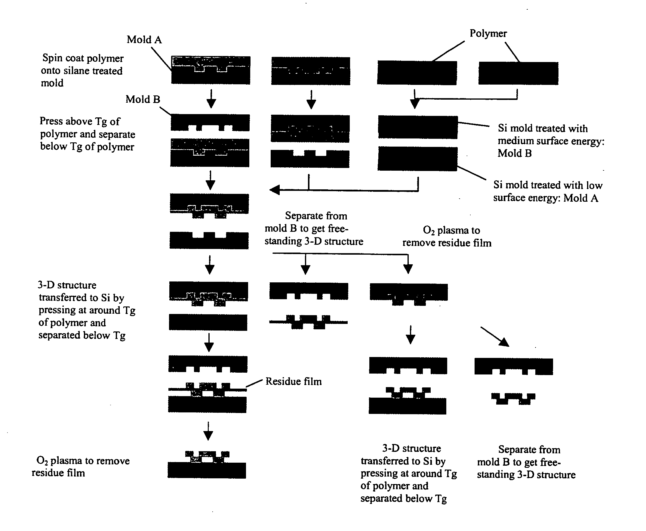
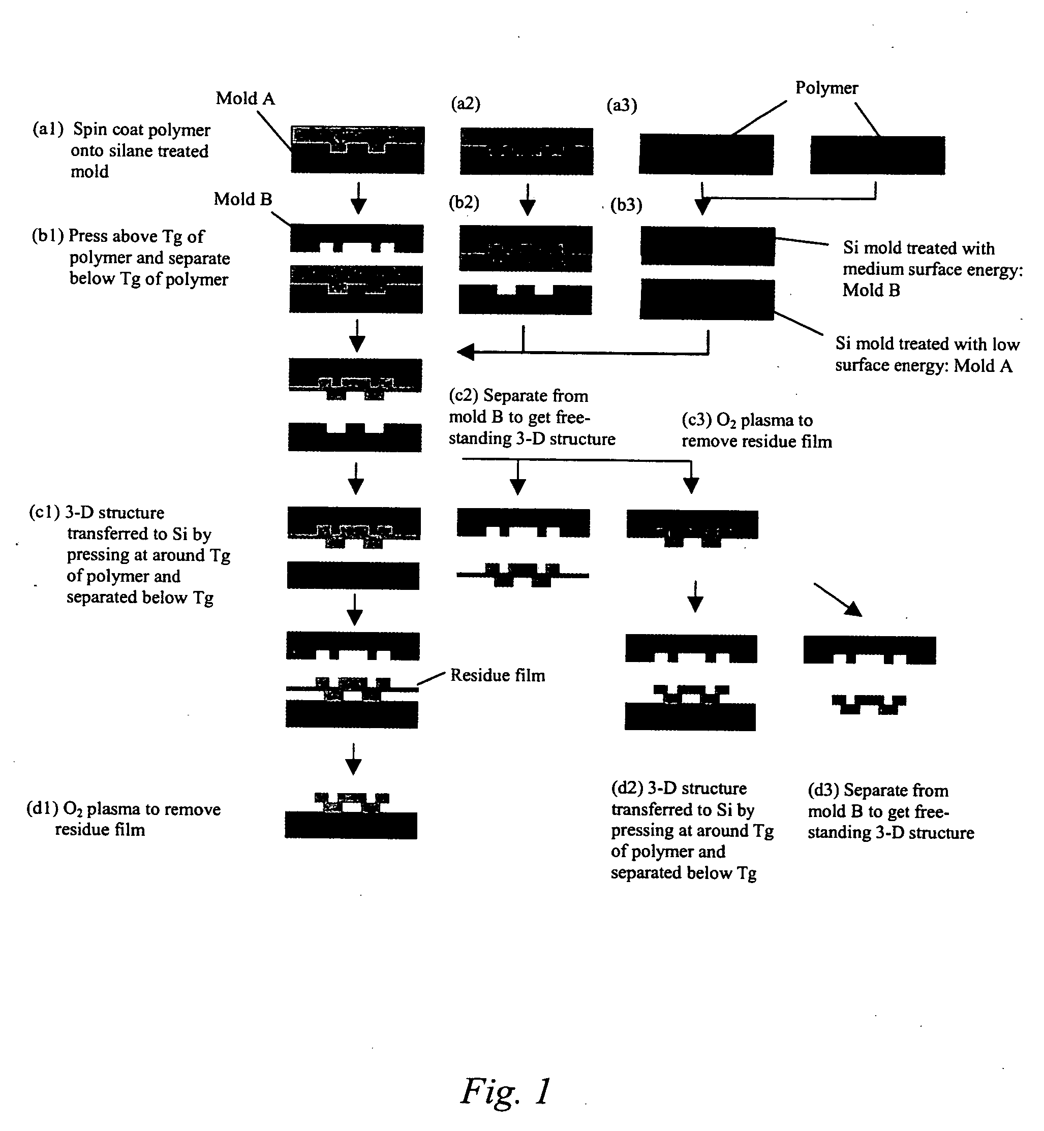
[0016] In some embodiments of the present invention, a duo-mold approach is employed in the above-described methods. In some embodiments, surface treatments are employed to impart differential surface energies to different molds and/or different parts of the mold(s). Such surface treatments, often in combination with differences in polymer glass transition temperatures, permit the formation of three-dimensional (3-D) micro- and/or nano-structures through imprinting and the transfer of such structures to a substrate. In some or other embodiments, such surface treatments can facilitate separation of the 3-D structures from the molds to form free-standing micro- and/or nano-structures individually and/or in a film. In some embodiments, such surface treatments can involve silanes, coatings, plasma deposition or treatment, and/or grafting treatments.
[0017] In some embodiments of the present invention, supported or free-standing stacked 3-D micro- and/or nano-structures are fabricated by using polymers of progressively lower glass transition temperatures or with miscible polymer blends. In some or other embodiments, a “latch-on” assembly technique is utilized to form supported and/or free-standing stacked micro- and/or nano-structures that enable the assembly of polymers without a glass transition temperature and eliminate the heating required to assemble thermoplastic polymers.
[0018] The present invention provides for novel methods in which to imprint supported and/or free-standing 3-D micro- and/or nano-structures. Such novel methods have a number of advantages over the existing prior art. First, the present invention provides for direct patterning methods that do not require a sacrificial lay...

Problems solved by technology

While X-ray and ion beam lithography have been demonstrated as viable alternative techniques for creating pattern dimensions below this limit, they are expensive.
However, it is time consuming and, like X-ray and ion beam lithography, expensive.
The above-mentioned lithographic techniques are further limited to fabrication of 2-D and supported features.
While 2-D fabrication techniques are mature technology down to the sub-micrometer scale, very little has been reported regarding 3-D sub-micrometer fabrication techniques.
Currently, of the limited amount of literature available on sub-micrometer 3-D fabrication techniques, most reports are seen to be mere extensions of various photolithography techniques.
While most of these techniques have demonstrated the feasibility of creating 3-D sub-micrometer or nanometer scale features, they are not easily implemented for mass production.
OLED-based displays fabricated using shadow-mask technology (FIG. 11) are difficult to fabricate because one must accurately align multiple layers of deposited material using shadow masks, and the masks tend to clog.
Moreover, it is difficult to fabricate features smaller than about 300 μm by 300 μm using a shadow mask, whereas OLEDs smaller than about 100 μm by 100 μm, and possibly smaller than about 10 μm by 10 μm, are generally desirable for high-resolution, full-color flat panel displays.
However, the organic materials used to fabricate OLEDs may be quickly degraded from exposure to deleterious substances su...

Method used


Image

  • Method of imprinting shadow mask nanostructures for display pixel segregation
  • Method of imprinting shadow mask nanostructures for display pixel segregation
  • Method of imprinting shadow mask nanostructures for display pixel segregation

Examples


example 1

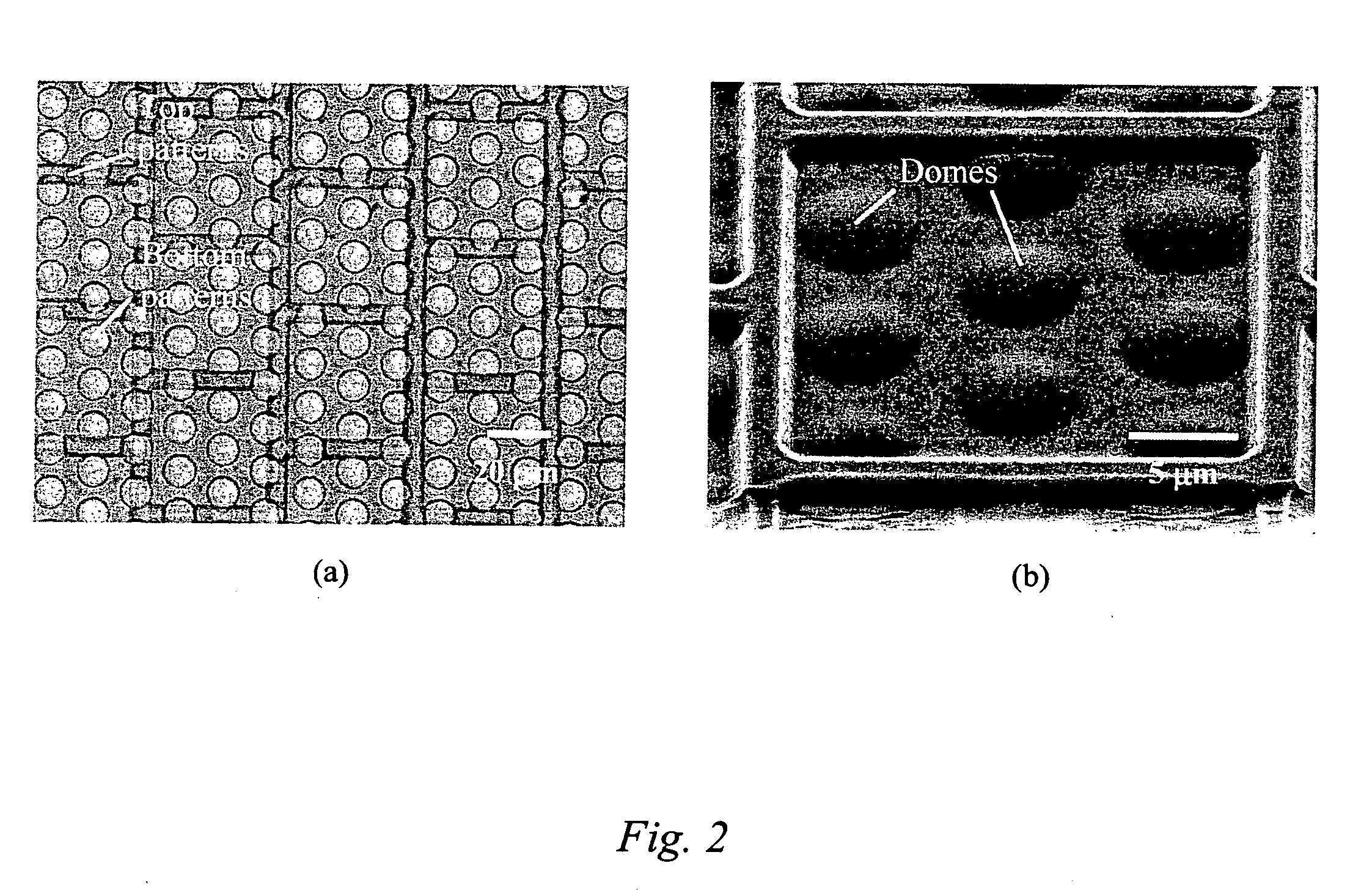
[0079] This Example serves to illustrate some types of 3-D micro-structures that can be formed using methods of the present invention.

[0080]FIG. 2(a) depicts an optical micrograph of an imprinted 3-D structure supported on a Si substrate comprised of 20 μm wide squares on the top and 5 μm diameter circular cavities on the bottom, wherein such structures are produced by duo-mold imprinting methods of the present invention. The structures are fabricated according to the following steps:

[0081] 1) Mold A is a Si mold comprising 5 μm diameter circular pillars of height 900 nm. Mold A is treated with a 20 mM silane solution (in n-heptane) of FDTS that results in a low surface energy mold. Note that in this Example, molds A and B have been pre-patterned with conventional photolithography, wherein the patterns are transferred onto the silicon with a plasma etch.

[0082] 2) Mold B is a Si mold comprising 20 μm wide squares of height 900 nm. Mold B is treated sequentially with PEDS and ODS s...

example 2

[0085] This Example serves to illustrate an embodiment that falls within the context of sub-process B, described above.

[0086]FIG. 3 illustrates an example of an imprinted 3-D structure supported on Si. The structure comprises a grating of 700 nm pitch with a 1:1 duty cycle on the top with 3 and 5 μm wide square cavities on the bottom. The two molds that were used to form this structure comprise the following:

[0087] 1) Mold A is a Si mold of 3 and 5 μm wide squares of height 250 nm. Mold A is treated with a 20 mM silane solution (in heptane) of FDTS that results in a low surface energy mold.

[0088] 2) Mold B is a Si grating mold of 700 nm pitch with a 1:1 duty cycle and height 350 nm. Mold B is also treated with a 20 mM silane solution (in heptane) of FDTS that also results in a low surface energy mold.

[0089] An 8 wt. % PMMA (average MW ˜15 kg / mol) in toluene solution is spin-coated at 3000 rpm for 30 seconds onto mold B to obtain a planarized coating with a thickness of around 50...

example 3

[0092] This Example serves to better illustrate how stacked 3-D polymeric micro- or nano-structures can be formed using polymer materials of progressively lower Tg.

[0093] The duo-mold imprinting of polymers with progressively lower glass transition temperatures or of miscible polymer blends (to tune the transition from glassy behavior to viscoelastic behavior) enable the formation of stacked 3-D structures as illustrated in FIG. 4. A representative three-polymer system suitable for the formation of such stacked 3-D structures is polycarbonate (average MW ˜18.2 kg / mol, Tg ˜150° C.), PMMA (average MW ˜15 kg / mol, Tg ˜105° C.), and poly(t-butyl-acrylate) (average MW ˜100 kg / mol, Tg ˜43° C.). In such a scenario, the first polymer to be imprinted with the duo-mold process would be polycarbonate, followed by PMMA, and finally poly(t-butyl-acrylate).

[0094] Alternatively, one could eliminate the use of progressively lower glass transition temperatures for the formation of stacked 3-D struc...


PUM

PropertyMeasurementUnit
Flexibilityaaaaaaaaaa
Aspect ratioaaaaaaaaaa
Surface energyaaaaaaaaaa

Abstract

The present invention is directed to micro- and nano-scale imprinting methods and the use of such methods to fabricate supported and/or free-standing 3-D micro- and/or nano-structures of polymeric, ceramic, and/or metallic materials, particularly for pixel segregation in OLED-based displays. In some embodiments, a duo-mold approach is employed in the fabrication of these structures. In such methods, surface treatments are employed to impart differential surface energies to different molds and/or different parts of the mold(s). Such surface treatments permit the formation of three-dimensional (3-D) structures through imprinting and the transfer of such structures to a substrate. In some or other embodiments, such surface treatments and variation in glass transition temperature of the polymers used can facilitate separation of the 3-D structures from the molds to form free-standing micro- and/or nano-structures individually and/or in a film. In some or other embodiments, a “latch-on” assembly technique is utilized to form supported and/or free-standing stacked micro- and/or nano-structures that enable the assembly of polymers without a glass transition temperature and eliminate the heating required to assemble thermoplastic polymers.

Description

CROSS-REFERENCE TO RELATED APPLICATIONS [0001] The present application is a continuation-in-part of U.S. patent application Ser. No. 10 / 852,448, filed May 24, 2004.TECHNICAL FIELD [0002] The present invention relates in general to micro- and nano-imprinting techniques, and in particular, to the use of novel micro- and nano-imprinting techniques for the purpose of making supported three-dimensional micro- and nano-structures for pixel segregation in OLED-based displays. BACKGROUND INFORMATION Two- and Three-Dimensional Fabrication Techniques [0003] Conventional photolithography is believed to be limited to about 150 nm in pattern dimensions. While X-ray and ion beam lithography have been demonstrated as viable alternative techniques for creating pattern dimensions below this limit, they are expensive. E-beam lithography has also been proven as a viable technique. However, it is time consuming and, like X-ray and ion beam lithography, expensive. In contrast to such lithographic techn...

Claims


Application Information

Patent Timeline
IPC IPC(8): B28B11/08B29C59/02B81C1/00B81C99/00B82B3/00G03C5/00G03F7/00
CPCB81C99/0085B81C2201/034B81C2203/032B81C2203/038Y10T428/254B82Y40/00G03F7/0002Y10T428/24479B82Y10/00B28B3/06B27N3/08A61M25/00
Inventor DUMOND, JARRETTLOW, HONG YEE
Owner AGENCY FOR SCI TECH & RES
Why Eureka
Try Eureka