Curing accelerator for curing resin, curing resin composition, electronic component device and method for producing phosphine derivative

Inactive Publication Date: 2005-12-01
HITACHI CHEM CO LTD
View PDF3 Cites 17 Cited by
  • Summary
  • Abstract
  • Description
  • Claims
  • Application Information

AI Technical Summary

Benefits of technology

[0154] The inorganic filler (E) may also preferably have an average particle diameter ranging from 1 to 50 μm, and particularly preferably from 10 to 30 μm. If it has an average particle diameter smaller than 1 μm, the resin composition tends to increase in viscosity. If it has an average particle diameter larger than 50 μm, the resin component and the filler tend to separate from each other, so that the cured product tends to be non-uniformly formed or have varied properties and also any narrow gaps in a mold tend to be low filled.
[0155] From the viewpoint of flow properties, the inorganic filler (E) may preferably have a particle shape which is spherical rather than rectangular, and may preferably have a particle size distribution in a wide range. For example, when the filler is mixed in an amount of 60% by weight or more, 70% by weight or more of the particles may preferably be spherical and be size-distributed in a wide range of from 0.1 to 80 μm. Such filler can readily provide a excellent fill structure, and hence may cause less increase in viscosity of materials even when mixed in a large quantity, so that compositions having superior flow properties can be obtained.
[0156] An anion exchanger can be optionally mixed with the curing resin composition of the invention. When the curing resin composition is used as the encapsulation molding material, it is preferable to add an anion exchanger from the viewpoint of an improvement in moisture resistance and high-temperat

Problems solved by technology

As a result, when the IC package absorbs moisture, the absorbing moisture expands rapidly at the time of soldering, resulting in the package crack, therefore, this has become the great problem.
However, since the increasing amount of the inorganic filler causes the decrease in flow properties at the time of molding, faulty filling, faulty conduction due to breaking of bonding wires of IC chips, and the performance of molded products may lower, there is a limit in the increasing amount of the inorganic filler.
As a result, this technique can not be expected to bring about any remarkable improvement in the reflow cracking resistance.
Particularly, when the amine system curing accelerators such as phosphorus type curing accelerators such as triphenylphosphine, amine type curing accelerators such as 1,8-diazabicyclo [5.4.0]undecene-7 are used, the flow properties is low, and thereby this technique can not be expected to bring about any remarkable improvement in the reflow cracking resistance.
When the addition product is used as the curing accelerator, there is a problem in cu

Method used


Image

  • Curing accelerator for curing resin, curing resin composition, electronic component device and method for producing phosphine derivative
  • Curing accelerator for curing resin, curing resin composition, electronic component device and method for producing phosphine derivative
  • Curing accelerator for curing resin, curing resin composition, electronic component device and method for producing phosphine derivative

Examples


Example

Synthesis Example 1

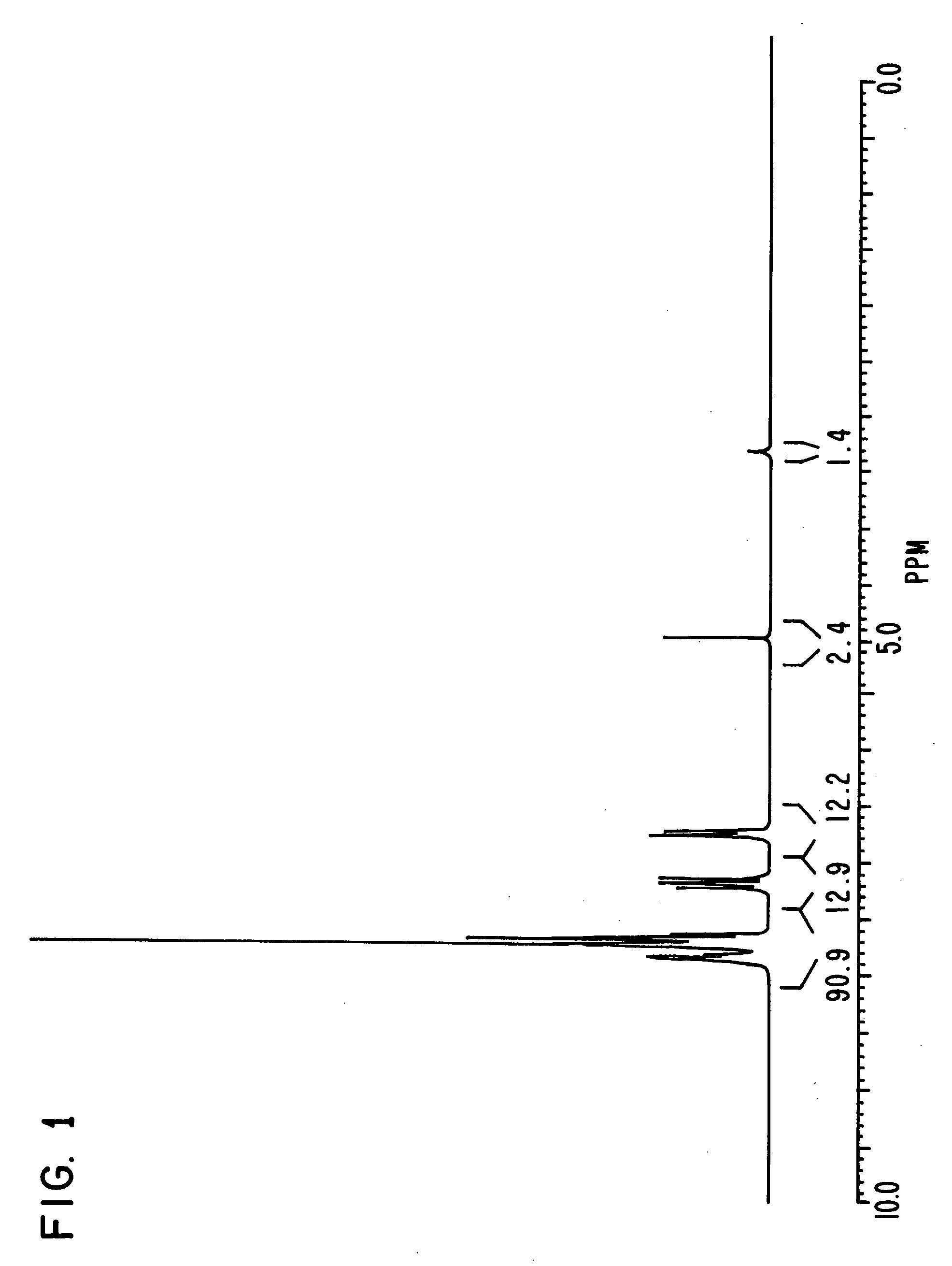
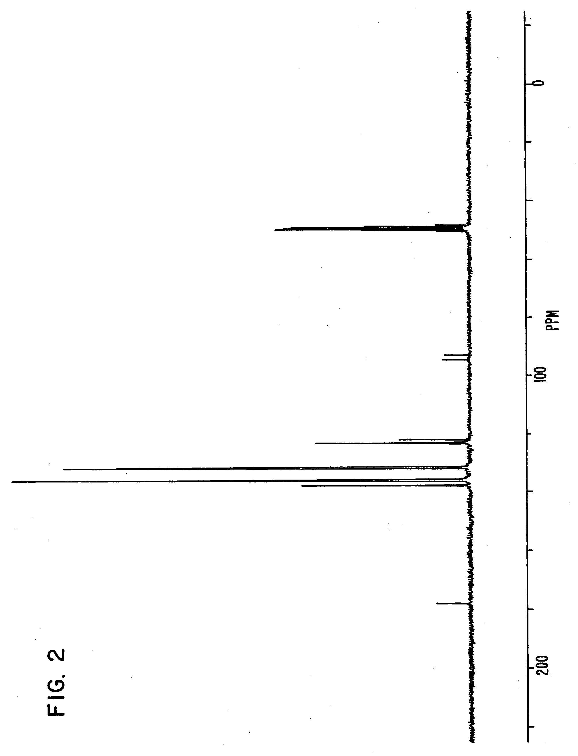
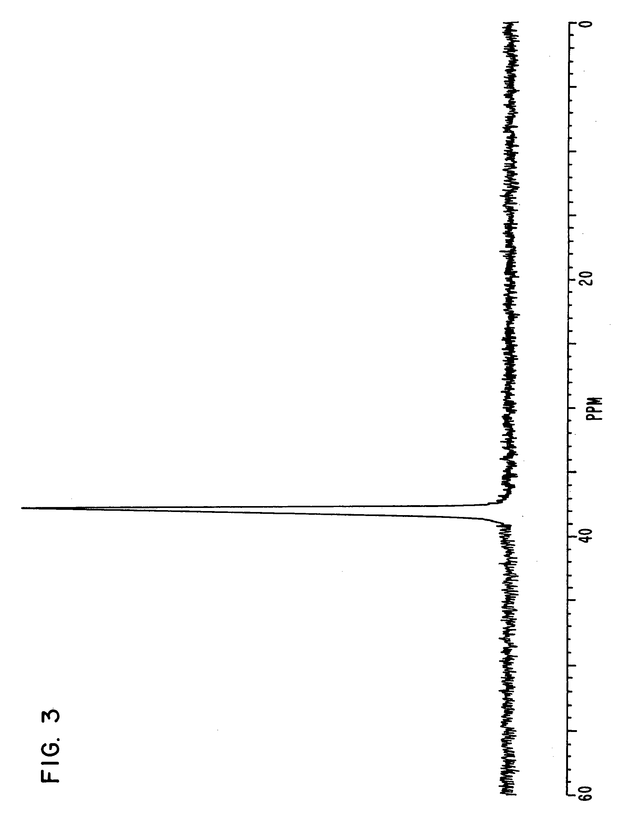
[0170] Triphenylphosphine of 20.4 g, 4-bromo phenol of 26.9 g, nickel (II) chloride hexahydrate of 3.5 g and DMF of 20 g were put in a flask, and were stirred at 145° C. for 6 hours. Under reduced pressure, the reaction liquid was concentrated, and methanol of 60 ml was added to the reaction liquid. Sodium hydroxide of 9.3 g was then added to the reaction liquid, and the reaction liquid was stirred until the sodium hydroxide was completely dissolved.

[0171] The solution obtained was filtered on celite, and was concentrated under reduced pressure until the whole amount became about 50 ml. The solution was then turned on into water of 1 liter, and the crystal deposited was filtered. The crystal was then dried under reduced pressure after washing, and a compound of 25.6 g was obtained. Elementary analysis revealed that C was 81.34 and H was 5.40 as calculated values (%), and C was 81.21 and H was 5.34 as measured values (%).

Example

Synthesis Example 2

[0172] A compound of 24.5 g was obtained in the same manner as in Synthesis Example 1 except that 4-chlorophenol of 20 g was put in place of 4-bromo phenol. Elementary analysis revealed that C was 81.34 and H was 5.40 as calculated values (%), and C was 81.23 and H was 5.33 as measured values (%).

Example

Synthesis Example 3

[0173] Triphenylphosphine of 20.4 g, 3-bromo phenol of 26.9 g, nickel (II) chloride hexahydrate of 3.5 g and DMF of 20 g were put in a flask, and were stirred at 145° C. for 6 hours. Under reduced pressure, the reaction liquid was concentrated, and methanol of 60 ml was added to the reaction liquid. Sodium hydroxide of 9.3 g was then added to the reaction liquid, and the reaction liquid was stirred until the sodium hydroxide was completely dissolved. The solution obtained was filtered on celite, and was concentrated under reduced pressure until the whole amount became about 50 ml. The solution was then turned on into water of 1 liter. The resultant solution was concentrated until the resultant solution become about 200 ml, and the crystal deposited was filtered. The crystal was then dried, and a compound of 10.2 g was obtained. Elementary analysis revealed that C was 81.34 and H was 5.40 as calculated values (%), and C was 81.15 and H was 5.29 as measured values ...


PUM

PropertyMeasurementUnit
Structureaaaaaaaaaa

Abstract

The invention relates to a curing accelerator for a curing resin obtained by reacting a phosphine compound (a) with a compound (b) having at least one halogen atom substituted on an aromatic ring and at least one proton atom which can be discharged, and subjecting the reaction product to dehydrohalogenation, a curing resin composition containing the curing accelerator, and an electronic component device having a device component encapsulated with the curing resin composition. The curing accelerator exhibits superior curability under moisture absorption, flow properties, reflow cracking resistance and high-temperature storage characteristics.

Description

BACKGROUND OF THE INVENTION [0001] 1. Field of the Invention [0002] The invention relates to a curing accelerator for a curing resin, a curing resin composition using the curing accelerator, suitable for molding materials, laminated sheet materials or adhesive materials, an electronic component device provided with device components encapsulated with the curing resin composition, and a method for obtaining a phosphine derivative used for the curing accelerator. [0003] 2. Description of the Related Art [0004] Curing resins such as an epoxy resin are conventionally used in a wide range as molding materials, laminated sheet materials and adhesive materials. Since these curing resins require rapid curability from the viewpoint of the productivity improvement, compounds for accelerating the curing reaction, that is, curing accelerators are widely used. Of the curing resins, especially, epoxy resin compositions are in wide use in the field of the encapsulation of device components in elec...

Claims


Application Information

Patent Timeline
IPC IPC(8): C08G59/68
CPCC08G59/688
Inventor NAKAMURA, SHINYAKATAYOSE, MITSUONAKAMURA, KAYOKO
Owner HITACHI CHEM CO LTD
Why Eureka
Try Eureka