Electrochemical cell

a technology of electrochemical cells and cell membranes, applied in the field of electrochemical cells, can solve the problems of increasing internal resistance, increasing capacity, and increasing voltage to be applied, and achieves the effects of increasing the resistance of internal components

Inactive Publication Date: 2006-02-16
SEIKO INSTR INC
View PDF7 Cites 54 Cited by
  • Summary
  • Abstract
  • Description
  • Claims
  • Application Information

AI Technical Summary

Benefits of technology

[0030] By resistance-welding the container and the sealing plate in the inert atmosphere like the electrochemical cell according to the invention, the electrolyte can be prevented from being oxidized by the heat at the welding time and deteriorating.

Problems solved by technology

Although the above electrochemical cell has been sealed by welding the container and the sealing plate in the atmospheric air, an internal resistance increase and a capacity decrease have become problems.
A voltage is applied to an inside of the electrochemical cell, where the corrosion is liable to progress and, especially if an organic solvent is used in the electrolyte, the voltage to be applied becomes high and thus the corrosion becomes severe.
Further, it causes a decrease in sealing strength and a generation of leak of the solution.
Additionally, by the decrease in sealing strength, since the electrochemical cell cannot endure an internal pressure increase at its heating time, its heat resistance decreases as well.
The 2nd problem to be solved is an oxidation of the organic solvent by a welding heat at the sealing time.
In the conventional electrochemical cell, although the container and the sealing plate have been welded in the atmospheric air, there has been a possibility that the organic solvent used in the electrolyte is oxidized and deteriorates by the welding heat and sparks generated at a welding time.
This low viscosity solvent is liable to be oxidized.

Method used


Image

  • Electrochemical cell
  • Electrochemical cell
  • Electrochemical cell

Examples


embodiment 1

[0051] Embodiment 1

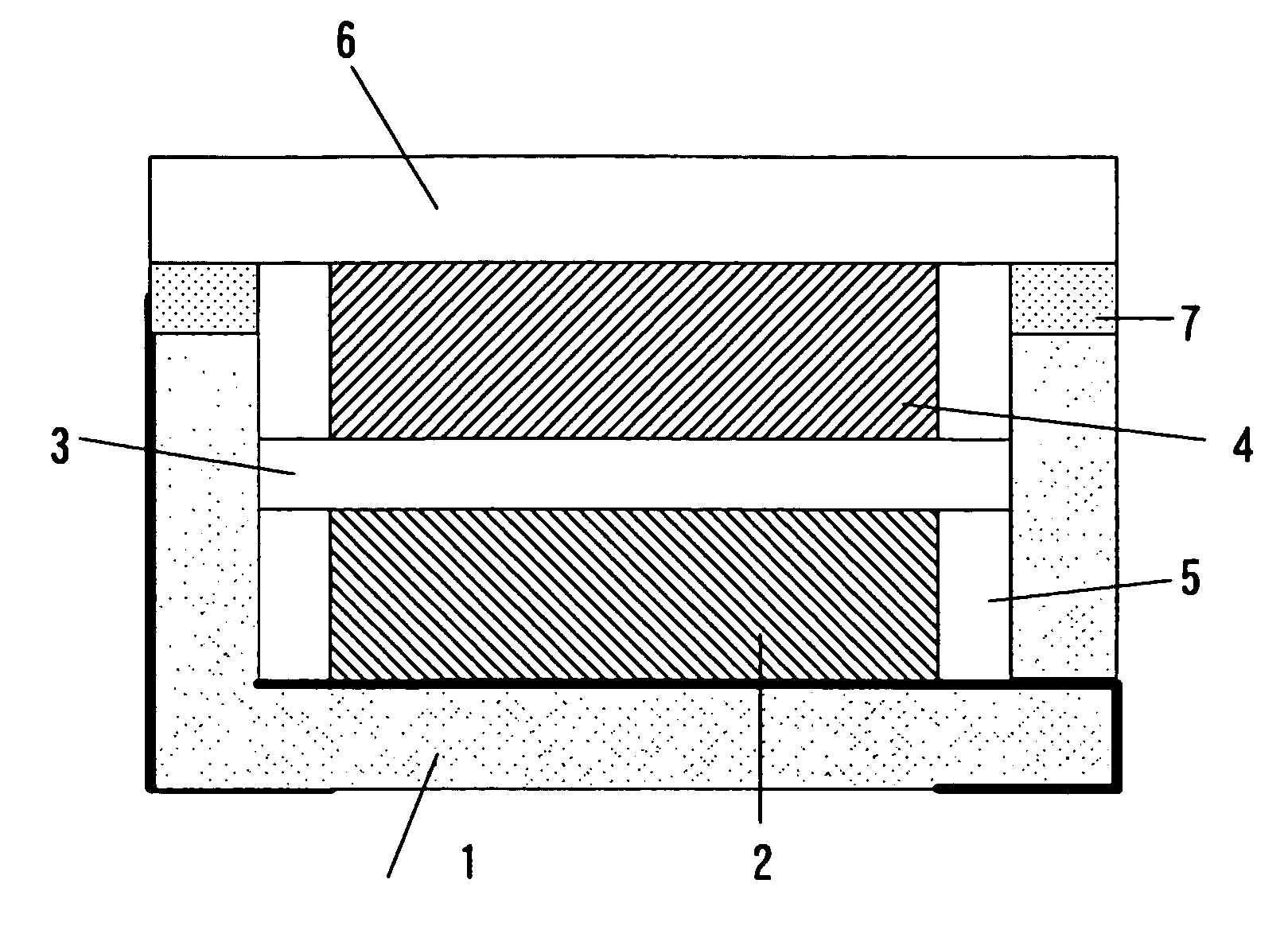
[0052] An electrical double layer capacitor was made by using an accommodation container of a shape similar to FIG. 1. The container 1 is made of alumina, and its size is 5×5×1 mm. A nickel plating layer is formed in the side wall end part of the container 1, and the sealing plate 6 and the container 1 are welded through the nickel plating layer. A concave dent was made 0.6 mm in depth, and 3×4 mm in size. A wiring of each of the 1st connection terminal and the 2nd connection terminal was one in which the gold plating was applied to a tungsten upper part. As the sealing plate, there was used an iron-cobalt alloy plate of 0.15 mm in thickness.

[0053] Each of the electrode 2 and the electrode 4 is 2×3 mm and 0.15 mm in thickness, and was made by compression-molding activated carbon with fluororesin being used as a binder. The 1st electrode 2 was bonded to a bottom part of the concave container 1 by an electrically conductive adhesive. The 2nd electrode 4 was bonded ...

embodiment 2

[0054] Embodiment 2

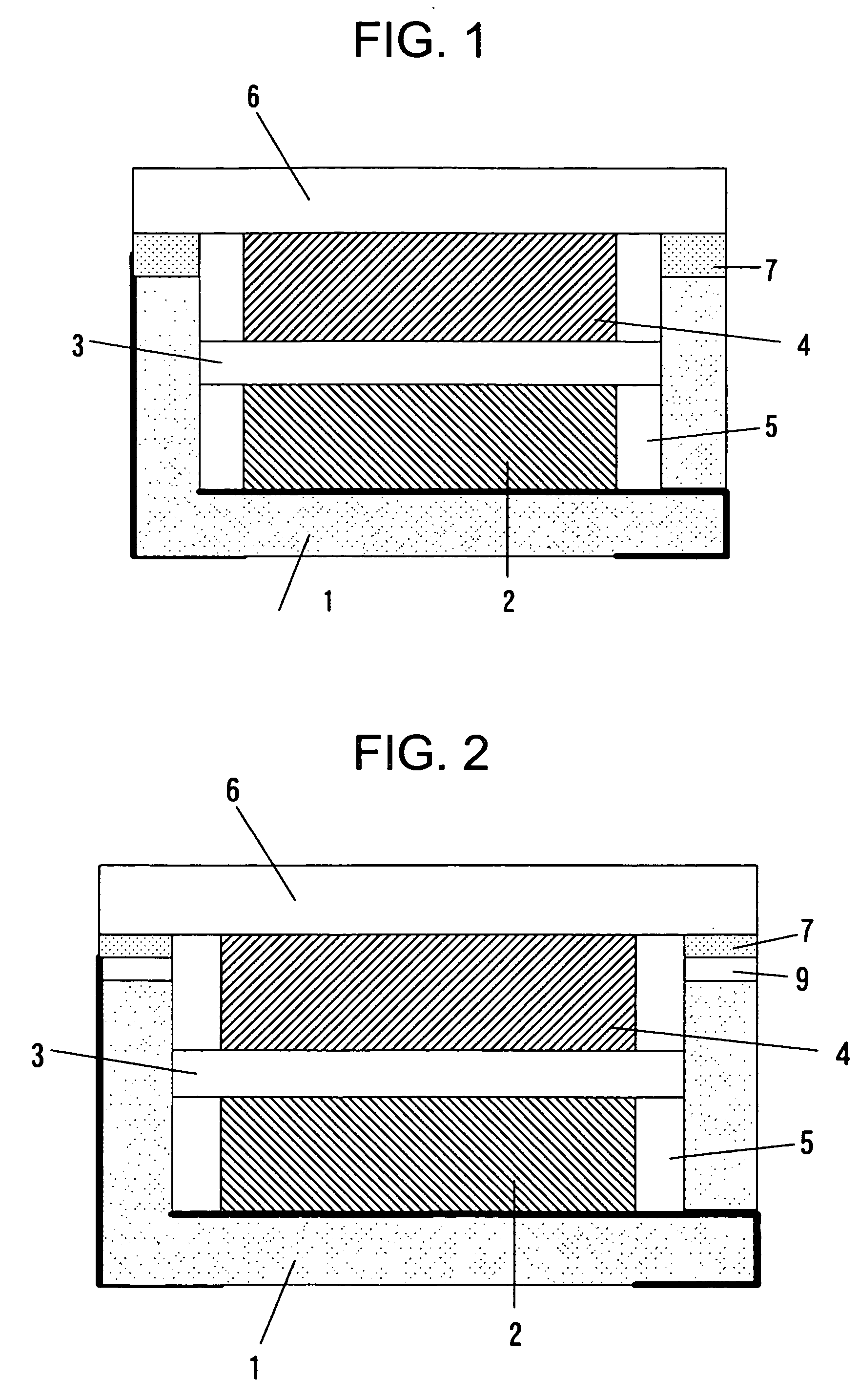
[0055] Similarly, the Embodiment 2 was made by using the container 1 of a shape similar to that of FIG. 2. As the electrode, the separator and the electrolyte, they were used same ones as the Embodiment 1. The container 1 is made of alumina, and its size is 5×5×1 mm. The metal ring 9 in which the nickel plating had been applied to the iron-cobalt alloy was joined to the side wall end part of the container 1 by using the silver blazing filler. The concave dent was made 0.6 mm in depth, and 3×4 mm in size. The wiring of each of the 1st connection terminal and the 2nd connection terminal was one in which the gold plating was applied to the tungsten upper part. As the sealing plate, there was used the iron-cobalt alloy plate of 0.15 mm in thickness.

[0056] Next, as to the Embodiment 1 and the Embodiment 2, which had been thus made, the reflow soldering was performed by actually applying a cream solder to a position of the connection terminal on the board. Although a h...

embodiment 3

[0061] Embodiment 3

[0062] The Embodiment 3 is explained below. It is the electrochemical cell in which epoxy resin was used as the container. A sectional view of the electrochemical cell is the same as in FIG. 2.

[0063] As a resin used in the container, there are suited polyphenylene sulfide, polyethylene terephthalate, polyamide, polyimide, polyetherether-ketone, liquid crystal polymer, and epoxy resin. By using the resin in the container, it is possible to inexpensively make the container.

[0064] The electrode and the electrolyte used were the same as in the Embodiment 1. The connection terminals, the metal ring 9 and the epoxy resin are insert-molded, thereby forming the container 1. As the 1st connection terminal and the 2nd connection terminal, a metal plate is used. The 2nd connection terminal and the metal ring 9 are electrically connected. The metal plate and the epoxy resin are insert-molded, and the 1st connection terminal, the 2nd connection terminal and the metal ring 9 ...


PUM

PropertyMeasurementUnit
temperaturesaaaaaaaaaa
sizeaaaaaaaaaa
thicknessaaaaaaaaaa

Abstract

In a conventional electrochemical cell, since a welding between a container and a sealing plate is performed in the atmospheric air, a weld zone is oxidized and a corrosion resistance decreases. For this reason, impurities are eluted from the weld zone into an electrolyte, and this causes an internal resistance increase and a capacity decrease of the electrochemical cell. Further, there is a possibility that an organic solvent in the electrolyte is oxidized by the welding. According to the invention, in order to solve the above problems, the seal welding between the container and the sealing plate of the electrochemical cell is performed under an inert atmosphere.

Description

BACKGROUNG OF THE INVENTION [0001] 1. Field of the Invention [0002] The present invention relates to an electrochemical cell. [0003] 2. Description of the Related Art [0004] The electrochemical cell such as nonaqueous electrolyte secondary battery and electrical double layer capacitor has such characteristics as high energy density, light weight and small size, and has been used as a backup electric source of a timepiece function of a portable equipment, a backup electric source of a semiconductor memory, and the like. For these portable equipments, there are required a reduction in size, a reduction in weight and an increase in function, and there is demanded an additional high density mounting of the electrochemical cell. [0005] Further, it is so adapted that, when the electrochemical cell is mounted to a circuit board, a reflow soldering method is generally used. The reflow soldering method is a method in which, after a solder cream has been applied to a portion, of the circuit b...

Claims


Application Information

Patent Timeline
Patent Type & Authority Applications(United States)
IPC IPC(8): H01M2/08H01M10/04H01G9/00H01G9/08H01G9/10H01G11/00H01G11/38H01G11/42H01G11/78H01G11/80H01G11/82H01G11/84H01G11/86H01M10/05H01M10/0566H01M10/058H01M50/184H01M50/186
CPCH01M2/0426H01M2/065H01M2/08H01M10/052Y10T29/49108H01G11/04Y02E60/13Y10T29/4911Y10T29/49114H01M10/058Y02E60/10H01M50/169H01M50/186H01M50/191Y02P70/50H01M50/184
Inventor KIDA, TOMOHIKOONODERA, HIDEHARUWATANABE, SHUNJITAHARA, KENSUKENAKAMURA, YOSHIBUMI
Owner SEIKO INSTR INC
Why Eureka
Try Eureka