
Carbon Neutralization System (CNS) for CO2 sequestering

a carbon neutralization and co2 technology, applied in the field of photobioreactors, can solve the problems of increasing the amount of heat trapped near the earth instead of escaping, increasing sea levels, and loss of wildlife, so as to increase the energy efficiency of the system, reduce energy costs, and reduce the effect of energy consumption

Inactive Publication Date: 2007-04-26
SAUDI ARABIAN OIL CO
View PDF13 Cites 60 Cited by
  • Summary
  • Abstract
  • Description
  • Claims
  • Application Information

AI Technical Summary

Benefits of technology

[0019] The current invention includes a continuous process photo-bioreactor and method of operating said bioreactor using flashing light emitting diodes (“LED's”) to artificially force and accelerate chlorophyll based photosynthesis in blue green algae (cyano-bacteria) and other related, uni-cellular organisms, either naturally occurring, derived there from, manipulated / created by artificial means or otherwise cultivated. The LED's preferably emit light tightly centered on a wavelength of 660 nm to optimize carbon dioxide sequestration while minimizing energy costs. The sequestered carbon dioxide can emanate from, for example, flue gas stacks from large stationary sources such as power plants, cement works and the like that burn solid, liquid or gaseous hydrocarbons.
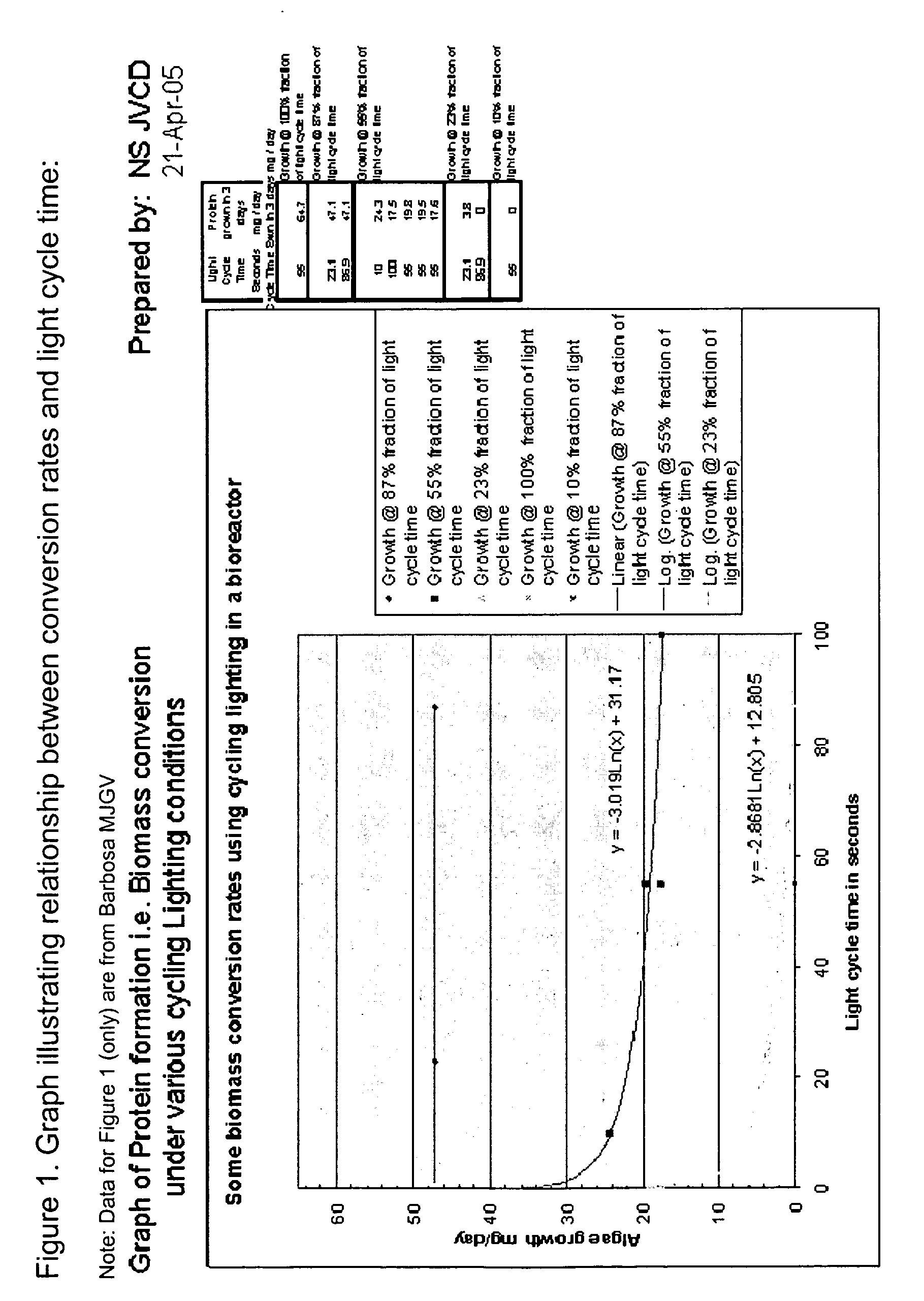
[0020] The increase in carbon dioxide sequestration is realized by accelerating and compressing the natural, day-night diurnal cycle to a fraction of its natural cycle time, preferably milliseconds, by flashing the LEDs. The minimization of the energy costs is achieved by electronically linking the LED's light cycle and light fraction time to the oxygen content and other measures of the culture (oxygen output being a measure of photosynthetic activity), so that the culture can be automatically kept at or near the maximum photosynthetic rate for the prevailing conditions of nutrients, gas flow, CO2 concentration, and the like. To achieve these results, it is anticipated that the “flash” will preferably last in the order of pico to micro seconds, and that the subsequent dark period will be in the approximate range of milli seconds up to about one second.
[0022] The process and apparatus would minimize energy costs in a number of ways. Much of the energy conservation is achieved by using carefully controlled flashing LED's that emit light tightly centered on a wavelength of 660 nm. The photon (light) stream from the LED's is intermittent (i.e. broken up), which saves energy as compared to continuous lighting. The LED's preferably emit light only at the very narrow wavelength required by the chlorophyll in the algae, which increases the energy efficiency of the system. Furthermore, the light-dark cycle times are controlled so as to match the overall photosynthesis cycle (PS I+PS II+the dark [Calvin] cycle), thus maximizing carbon dioxide uptake. Phyto-inhibition, which occurs at excessive light levels, is largely avoided, and the algae are photo-acclimated to grow in low average light levels.
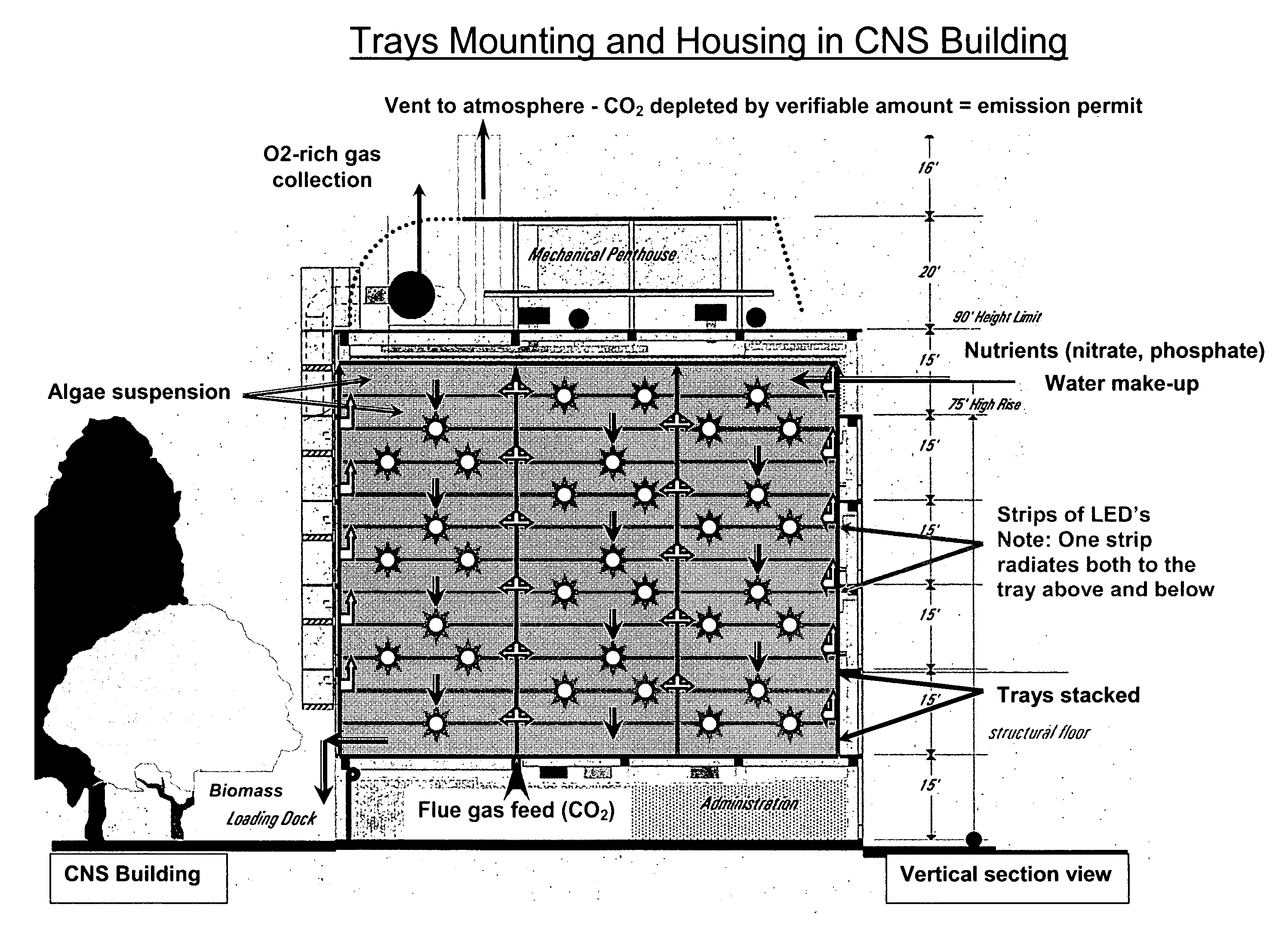
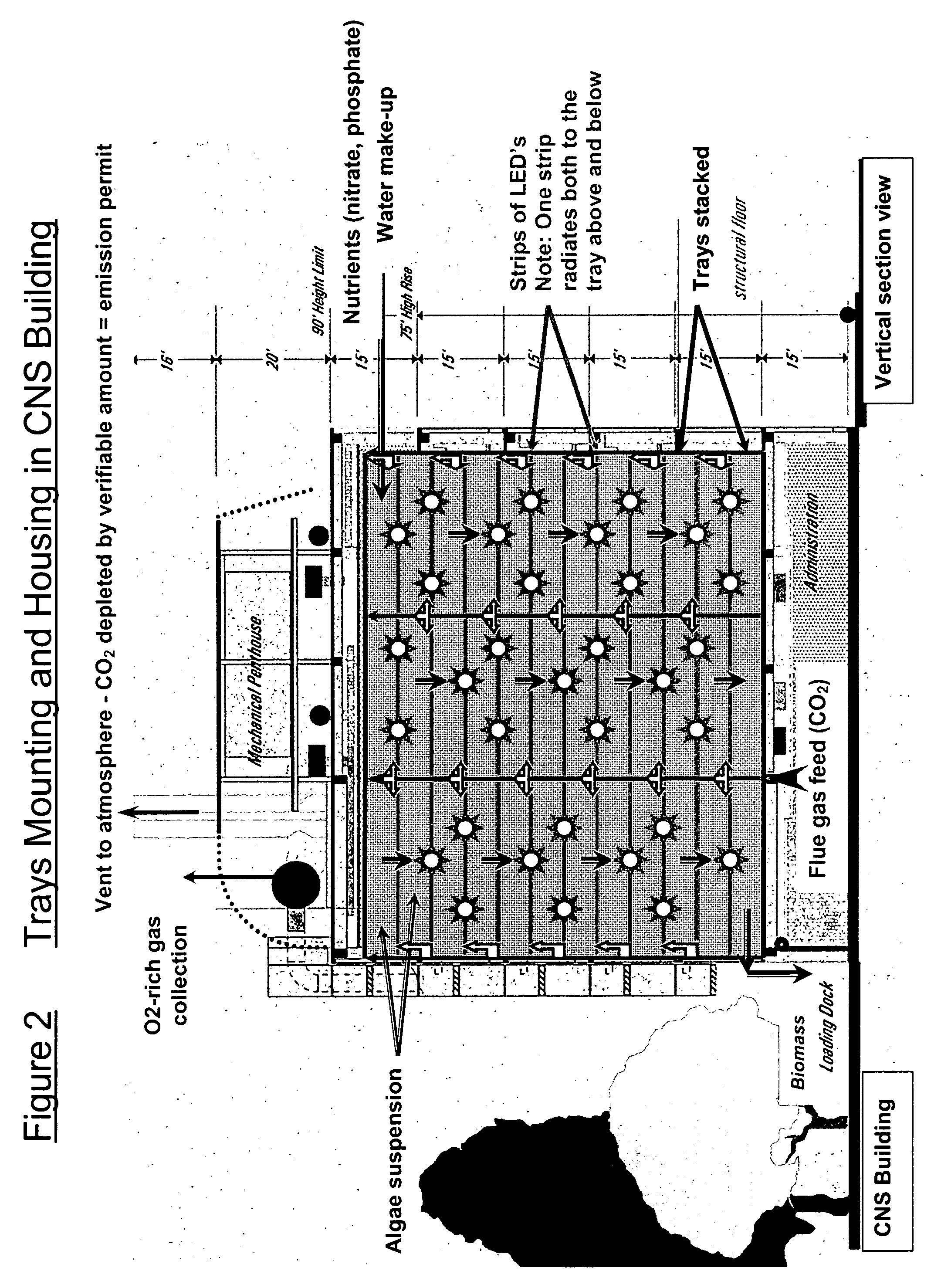
[0023] The bioreactor apparatus of the present invention preferably includes a sealed housing or building having a series of stacked, generally parallel trays running there through, each of wide rectangular profile. They are preferably inclined slightly from the horizontal. Energy savings are achieved by arranging the bioreactor horizontally, rather like the tubes in a contemporary, steam-raising boiler. This orientation saves energy because it obviates most of the mass flow and control problems that are seen in vertically arranged bio-reactors. Very little energy is expended in pumping a culture through a horizontal system, since most of the flow is achieved by orienting the horizontal bioreactor slightly downhill. As a result, most of the flow is due to gravity, with the remainder being achieved by the flowing of the gas. Due to the horizontal orientation, only minimal energy is needed to run the pump to return the aquatic culture to the top end of the bioreactor. For instance, a low-pressure, “Archimedes Screw” pump can be used to gently return the aquatic culture to the top end of the reactor using very little energy. The water cycle within the system is almost closed, only requiring makeup water to compensate for some evaporation through the gas vents, and some water entrained with the harvested algae.
[0024] As a further advantage, because the reactor trays are modular, and hence stacked, the system is easily scaled, for example, from a 16 MW gas turbine right through a huge 16,000 MW power station. Such modularity of construction, and hence scalability, has not been seen in other photo-bioreactors. Further, the modular design allows different strains of bacteria to be grown in different groups of trays, if desired.
[0025] Finally, as the reactor trays are horizontal and modular, maintenance of the trays will be easy. For major overhauls, the trays can be pulled from the assembly, rather like the current procedure for cleaning and de-scaling boiler tubes. For intermittent, in-situ cleaning, which is important to avoid algal fouling of the LED's radiant surfaces, a low-power red laser can be swung to the ends of the temporarily emptied tray channel. The laser will quickly scan the interior of the channels in a pre-set pattern, thus burning off any organic residues without scratching the polycarbonate, optical surfaces. For longer tray lengths, a small, trolley-mounted red laser can be pulled through the tray while rotating rapidly in order to achieve de-fouling. It is known that live Chlamydomonas Reinhardtii cells can be made to rotate while pinned in a laser “trap.” The energy of the light beam can thus be used to manipulate and trap cells much like the way that the wind moves objects of a larger scale. Hence the laser approach described above can also be effective as a cleaning device in association with the present invention.

Problems solved by technology

As a result, increasing amounts of heat will be trapped near the earth instead of escaping into space.
These include higher average global temperatures, unpredictable weather, the melting of Antarctic, Arctic and glacial ice sheets, rising sea levels, and loss of wildlife.
In addition to environmental restraints, legal and administrative regulations restrict the release of carbon dioxide, and hence the burning of hydrocarbons.
Furthermore, there are potential legal actions that could be brought against some of the users of hydrocarbons, and by implication their hydrocarbon suppliers, on the grounds that they “knowingly and willfully” emit substances that are damaging to the environment.
Despite the existence of these technologies, there are currently no medium-term, fully viable alternatives to the burning of fossil fuels.
While natural slime ponds are able to sequester CO2, there are numerous problems associated with using this technique in a hydrocarbon fired power station.
However, the light source is not controllable, emits from the wrong spectrum for preferred CO2 sequestration and wastes energy.
The patent does not, however, teach intermittent LED lighting, nor does it teach delivering the 660 nm light required by chlorophyll to optimize carbon dioxide sequestration.
The patent does not, however, teach a preferred source for intermittent light.
Also, the agitator vanes would damage the cell walls, which would cause cell death.
This approach is limited, however, by the turbulent flow of the fluid, the hydraulic power requirement and by cell death due to cell wall rupture under hydrodynamic stress.

Method used


Image

  • Carbon Neutralization System (CNS) for CO2 sequestering
  • Carbon Neutralization System (CNS) for CO2 sequestering
  • Carbon Neutralization System (CNS) for CO2 sequestering

Examples


Embodiment Construction

[0031] The present invention includes a method and device for optimizing the sequestration of carbon dioxide while minimizing the energy costs. In a preferred embodiment, the device provides for the forced, artificially driven photosynthesis of cyano-bacteria (blue green algae) by the use of pulsed or flashing light emitting diodes as an artificial light source.

[0032] The device for the photofixation of CO2 of the present invention includes an outer wall defining a containment area. A CO2-rich gas source operable to provide CO2-rich gas into the containment area is also provided. A plurality of trays is housed within the containment area, the trays having a bottom and two sides. The trays are operable to circulate an aquatic culture of a photosynthetic organism operable to convert CO2-rich gas to O2-rich gas. The aquatic culture is circulated within the trays, that is, that the aquatic culture is moved generally down the tray while generally being maintained between the two sides. ...


PUM


Abstract

A device and method for carbon dioxide sequestering involving the use of a photo-bioreactor with Light Emitting Diodes (LED's) for the cost-effective photo-fixation of carbon dioxide (CO2). This device and method is useful for removing undesirable carbon dioxide from waste streams.

Description

RELATED APPLICATIONS [0001] This application is related to and claims priority and benefit of U.S. Provisional Patent Application Ser. No. 60 / 728,541, filed Oct. 20, 2005, titled “Carbon Neutralization System (CNS) for CO2 Sequestering,” which is incorporated herein by reference in its entirety.BACKGROUND OF THE INVENTION [0002] 1. Field of the Invention [0003] This invention generally relates to the field of carbon dioxide sequestering. More specifically, the present invention relates to a photo-bioreactor with pulsing Light Emitting Diodes (LED's) for the cost-effective photo-fixation of carbon dioxide (CO2). [0004] 2. Description of the Related Art [0005] Power stations burn fossil hydrocarbons such as coal, oil, and gas in order to meet the world's rampant demand for affordable energy. The combustion of these hydrocarbons releases large amounts of carbon dioxide into the atmosphere. For example, the combustion of a petroleum fuel such as liquid paraffinic oil produces up to thre...

Claims


Application Information

Patent Timeline
IPC IPC(8): A61L9/01C12M1/00C12N1/12A01G7/00
CPCC12M21/02C12M21/04C12M23/04C12M31/10Y02E50/343Y02E50/30Y02P60/20
Inventor SHEPPARD, NORMAN J.
Owner SAUDI ARABIAN OIL CO
Learn More