Furthermore, such techniques were also not used to control the flow of gas into and / or out of an airbag to tailor the airbag inflation characteristics to the size, position and / or
relative velocity of the occupant or other factors such as seatbelt usage, seat and seat back positions, headrest position, vehicle velocity, etc.
This is usually a
trial and error process wherein the engineer or
crash sensor designer observes data from crashes where the airbag is desired and when it is not needed, and other events, such as rough road and abusive incidents, where the airbag is not needed.
The resulting
algorithm is not universal and most such engineers or crash sensor designers will answer in the negative when asked whether their
algorithm will work for all vehicles.
These papers demonstrate, among other things, that there is no known theory that allows an engineer to develop an
algorithm for sensing crashes and selectively deploying the airbag except when the sensor is located in the crush zone of the vehicle.
These papers show that, in general, there is insufficient information within the acceleration
signal measured in the passenger compartment to sense all crashes.
In
spite of the problems associated with finding the optimum crash sensor algorithm, many vehicles on the road today have electronic
single point crash sensors.
Some of the problems associated with
single point sensors have the result that an out-of-position occupant who is sufficiently close to the airbag at the time of deployment will likely be injured or killed by the deployment itself.
Fortunately, systems are now being developed, and are in limited production, that monitor the location of occupants within the vehicle and can suppress deployment of the airbag if the occupant is more likely to be injured by the deployment than by the accident.
However, these systems are not believed to currently provide the information necessary for the control of airbag systems, or the combination of seatbelt and airbag systems, which have the capability of varying the flow of gas into and / or out of the airbag and thus to tailor the airbag to the size and / or weight of the occupant (and / or possibly another morphological characteristic of the occupant), as well as to the position, velocity and / or seatbelt use of the occupant.
These sensors are generally not sufficient for sensing side impacts as discussed in reference (11), however, they can be successful when used in conjunction with a passenger compartment mounted electronic sensor or as a safing sensor.
Other crush zone mounted crash sensors including crush switch designs where the width and height dimensions are comparable, must either be large and thus heavy, expensive and difficult to
mount, or there is a possibility that the randomly shaped crushed material which forms the boundary of the crush zone will bridge the sensor resulting in late triggering.
This crushed material frequently contains holes, wrinkles or folds or portions that may even be displaced or torn out during the crash with the result that it is difficult to guarantee that a particular small area where the sensor is mounted will be struck early in the crash.
It has been found that conventional designs of tape or ribbon switches have the drawback that the force required to close the switch is very small compared with the forces which are normally present in automobile crashes.
During routine maintenance of the vehicle, the normal tape switch may be damaged or otherwise made to close and remain closed, with the result that later, when the vehicle encounters a pot hole or other shock sufficient to cause the arming sensor to close, an inadvertent air bag deployment can result.
Similarly, if the tape switch is mounted on the front of the radiator support, which is a preferred mounting locating for crush zone sensors, hail, heavy rain, stones or other debris from the road might
impact the tape switch and cause a momentary closure or damage it.
If this happens when the vehicle experiences a shock sufficient to cause the arming sensor to close, an inadvertent air bag deployment might also occur.
This
system is not perfect, however, it has been shown to do a better job than any other
sensor system now in use.
This is because many people suffer
whiplash injuries at rather low velocity impacts and if an
inflatable restraint is used, the repair cost may be significant.
Since the rear of a vehicle typically has about one third of the stiffness of the vehicle front, electronic sensors will have even a tougher time discriminating between trigger and non-trigger cases for rear impacts.
Since there is very little
signal out of the crush zone where electronic sensors are mounted, electronic sensors alone are not able to discriminate airbag required crashes from other crashes not requiring
airbag deployment.
Thus, although they cannot be reliably used alone as a discriminating sensor for side impacts, the combined
system does function properly.
In use, when pressure is applied to the tube, it deforms at the location at which pressure is applied thereby coming into contact with the wire and causing a circuit to close.
Since neither of these can be assumed, the device will not provide a measurement of the impacting velocity and therefore at best can act as an
impact-sensing switch with some discriminating capability.
It is known that currently up to about 70% of vehicle occupants sit closer to the airbag than the average male and therefore such sensors trigger
airbag deployment late for such occupants placing them at risk of being injured by the airbag.
In
spite of these advantages, self-contained airbag systems have only achieved limited acceptance for frontal impacts and have so far not been considered for side impacts.
The “all-mechanical” self-contained systems were the first to appear on the market for frontal impacts but have not been widely adopted partially due to their sensitivity to accelerations in the vertical and lateral directions.
These cross-axis accelerations have been shown to seriously degrade the performance of the most common all
mechanical design that is disclosed in Thuen, U.S. Pat. No. 4,580,810.
Both frontal and
side impact crashes frequently have severe cross-axis accelerations.
Additionally, all-mechanical self-contained airbag systems, such as disclosed in the Thuen patent, require that the sensor be placed inside of the inflator which increases the strength requirements of the inflator walls and thus increases the size and weight of the system.
One
disadvantage of this system is that a hole must still be placed in the inflator wall to accommodate the percussion primer that has its own housing.
Another
disadvantage in the Thuen system that makes it unusable for side impacts, is that the arming system is sealed from the environment by an O-ring.
This sealing method may perform satisfactorily when the module is mounted in the protected passenger compartment but it would not be satisfactory for
side impact cases where the module would be mounted in the vehicle door where it can be subjected to water, salt,
dirt, and other harsh environments.
Self-contained electrical systems have also not been widely used.
In contrast to mechanical systems, the electronic sensor and diagnostic systems used by most vehicle manufacturers are expensive.
However, researchers now believe that there are a significant number of crashes which cannot be sensed in time in the passenger compartment and that this will require the addition of another sensor mounted in the crush zone (see, e.g., reference 5).
Some of these problems do not apply to side impacts mainly because side
impact sensors must trigger in a very few milliseconds when there is no significant
signal at any point in the vehicle except where the car is crushing or at locations rigidly attached to this crush zone.
These elongated prior art side impact crush-sensing switches are not readily adaptable to the more compact self-contained designs.
If a wire is severed during a crash but before the airbag deploys, the system may lose its power and fail to deploy.
This is more likely to happen in a side impact where the wires must travel inside of the door.
Finally, the space available for the mounting of airbag systems in the
doors of vehicles is frequently severely limited making it desirable that the airbag module be as small as possible.
If the gas is not permitted to enter the passenger compartment, the temperature of the gas can be higher and the products of
combustion can contain toxic chemicals, such as
carbon dioxide.
Although there has been a great deal of discussion on the use of anticipatory sensors for initiating restraint deployment, no practical systems have been developed other than those of the current assignee.
The basic problem has been that an airbag should not be deployed unless the approaching object can be identified as a serious
threat.
It is not surprising therefore that the electrical system in a vehicle is by far the most unreliable system of the vehicle and the probable cause of most warranty repairs.
Unfortunately, the automobile industry is taking a piecemeal approach to solving this problem when a revolutionary approach is called for.
This has resulted in many failures of the airbag system due to shorted wires and other related causes.
One problem with ceiling-mounted airbags is that the distance required for the airbag to travel, in some cases, is longer and therefore a larger airbag is needed with greater
deployment time.
The driver poses a different problem since it would be difficult to position a ceiling-mounted airbag module where the airbag would always be projected properly between the occupant and the
steering wheel.
This problem for the driver's airbag system is not the concept of mounting the airbag on the ceiling, but the design of the
steering wheel and
steering column.
The majority of vehicles manufactured today have power-assisted steering systems and, in fact, most drivers would have difficulty steering a car today if the
power steering failed.
Small people, for example, who are wearing seatbelts can still be seriously injured or killed in accidents as their faces slam into steering wheel hubs.
The problem of properly positioning an airbag, when the comfort and convenience features of telescoping and tilting steering columns are considered, results in substantial safety compromises.
Deployment-induced injuries which result when a small person is close to the steering wheel when the airbag deploys have already caused several deaths and numerous serious injuries.
In some accidents, an occupant, and particularly a center-seated occupant, can pass between the two airbags and not receive the full protection from either one.
There are airbag modules in use which are relatively large, heavy, expensive and inefficient.
As a result, airbags are now primarily only used for protecting the passenger and driver in a frontal impact, although most automobile manufacturers currently offer a small airbag providing limited protection in side impacts and many are now offering head protection or curtain airbags.
One reason for this is that there is a mismatch between the output of a burning propellant and the inflation requirements of an airbag.
Airbags, on the other hand, need gases with low temperatures and low pressures and high gas flow rates.
Such systems are considerably more energy efficient, however, they also require a container of
high pressure gas and monitoring of the pressure in that container.
Other systems have attempted to use aspiration techniques, but because of the geometry constraints of current car inflator designs and mounting locations, and for other reasons, currently used aspiration systems are only able to draw significantly less than 30% of the gas needed to inflate an airbag from the passenger compartment.
Furthermore, since inflators are large and inefficient, severe restrictions have been placed on the type of propellants that can be used since the
combustion products of the propellant must be breathable by automobile occupants.
It is of little value to save an occupant from death in an
automobile accident only to suffocate him from an excessive amount of
carbon dioxide in the air within the passenger compartment after the accident.
This
residual mass is very hot and requires the inflator to be mounted away from combustible materials further adding to the
mass and size of the airbag system and restricts the materials that can be used for the inflator.
It is a persistent problem in the art that many people are being seriously injured or even killed today by the airbag itself.
One reason that this is such a significant problem is that the airbag module itself is quite large and, in particular, the airbags are made out of thick, heavy material and packaged in a poor, folded geometry.
All of this heavy airbag material must be rolled and folded inside this comparatively small module, thus requiring substantial energy to unfold during deployment.
Even the time to deploy the airbag is substantially affected by the
mass of the airbag material and the need to unfold an airbag with a complicated folding pattern.
Although analysis indicates that pumping ratios of 4:1 or 5:1 would be difficult to achieve with this design as illustrated, nevertheless, this reference illustrates the size and rough shape of an aspirating system which is required to obtain high pumping ratios using the prior art designs.
No attempt has been made in this design to optimize the
nozzle geometry to make use of a converging-diverging
nozzle design, for example.
Analysis shows, however, that the opening needed for the claimed aspiration ratios would in general be far too large for it also to be used for exhausting the airbag during a crash.
This design also does not require use of aspiration valves which is more reasonable for this case, but still unlikely, since the aspiration port area is much smaller.
No attempt has been made to optimize the
nozzle design as is evident by the short nozzle length and the low pumping ratio.
Analysis has shown that this is the case, that is, that such large aspiration ratios are not achievable with the prior art designs.
Little attempt has been made to optimize the nozzle design.
The lack of commercial success of these two Hayashi patents is probably due to the fact that such high pumping ratios as claimed are not in fact achievable in the geometries illustrated.
This system however produces a gas which is too hot for use directly to inflate an airbag.
The steam can cause burns to occupants and
carbon dioxide in significant quantities is toxic.
Nevertheless, the airbag system disclosed is quite large and limited in length such that the flow passageways are quite large which requires a long nozzle design for efficient operation.
No analysis, however, is provided to prove that the area of the aspiration holes is comparable to the area of the exhaust holes normally provided in the airbag.
The nozzle design has not been optimized.
None of the prior art inflators are believed to contain the advantages of the combination of (i) a linear inflator having a small cross section thereby permitting an efficient nozzle design wherein the length of the nozzle is much greater than the aspiration port opening, (ii) a non
sodium aside propellant which may produce
toxic gas if not diluted with substantial quantities of
ambient air, and (iii) an inflator where minimal or no filtering or heat absorption is required.
It is interesting to note that in
spite of the large aspiration pumping ratios mentioned and even claimed in the prior art mentioned above, and to the very significant advantages which would result if such ratios could be achieved, none has been successfully adapted to an automobile airbag system.
One reason may be that pumping ratios which are achievable in a
steady state laboratory environment are more difficult to achieve in the transient conditions of an actual
airbag deployment.
None of these prior art designs has resulted in a thin linear module which permits the space necessary for an efficient nozzle design as disclosed herein.
In spite of the many advantages claimed in the prior art patents, none have resulted in a module which can be mounted within the vehicle headliner trim, for example, or can be made to conform to a curved surface.
In fact, the rigid shape of conventional airbag modules has forced the vehicle interior designers to compromise their designs since the surface of such modules must be a substantially flat plane.
However, Nissan has stated that it cannot provide more than a total of two airbags in the vehicle and that it will not offer a front passenger side airbag for those vehicles that have a rear seat airbag.
Side airbags will generally not deploy when the frontal airbags do because if more than two airbags would be deployed in a vehicle at the same time, the pressure generated by the deploying airbags within the passenger compartment of the vehicle creates large forces on the
doors.
These forces may be sufficient to force the
doors open and consequently, if the doors of the vehicle are forced open during a crash, vehicle occupants might be ejected, greatly increasing the likelihood of serious injury.
In addition, the pressure generated within the passenger compartment creates excessive
noise which can injure human beings.
In addition to airbags for side impacts and rear seats, it is likely that airbags will be used as knee bolsters since automobile manufacturers are having serious problems protecting knees from injury in crashes while providing the comfort space desired by their customers.
What has not been appreciated, however, is that once there is a significant opening from the vehicle to the outside, the requirements for the composition of the inflator gases used to inflate the airbags change and inflators which generate a significant amount of
toxic gas become feasible, as will be discussed below.
This is partially due to the fact that when
sodium aside burns, in the presence of an oxidizer, it produces large amounts of
Nitrogen gas.
It also produces
sodium oxide which must be retained in the inflator since
sodium oxide, when mixed with
moisture, becomes lye and is very toxic to humans.
In many cases, the gases produced by these other propellants are only toxic to humans if breathed over an extended period of time.
It is believed that in all current designs, a substantial amount of the energy in a propellant is lost through this cooling process which in turn necessitates that the inflator contains more propellant.
As a result, although numerous attempts have been made to create aspirated inflator systems, they have only been used on the passenger side and their efficiency has been low.
In view of the
large size of conventional
sodium azide inflators and woven airbags, there is limited room for the airbag system and it is difficult to design aspirating systems which will fit within the remaining available space.
Another reason for the low efficiency of aspirated inflator systems is that the aspirated systems used typically have inefficient nozzle designs.
Poole et al. does not suggest that the outside air should come from the passenger compartment and therefore does not provide a solution to the problem of excessive pressure being generated in the passenger compartment upon deployment of multiple airbags, as discussed above.
Although interesting materials, they may not be practical for airbags due to their high cost.
It is important to note that the particular formulations listed in Chen are probably poor choices for the blunting film portion of a laminated film used to make film airbags.
Thus, they will provide little resistance to the propagation of a tear in the higher modulus component of the laminated film and would be poor as the blunting layer.
Although these materials are considerably more expensive than NYLON®, for example, they are about twice as strong and therefore only half as much would be required.
However, if it is laminated to a more rigid material or a net as disclosed herein and in the previous patents of the current assignee, then again many of the advantages of the material are lost since the main material providing the strength to the airbag is the more rigid film or net layer.
In contrast, many occupants are out-of-position and many real world crashes involved highly angular impacts, spinouts, rollovers etc. where the occupant is frequently injured by the deploying airbag and impacts other objects in the vehicle compartment in addition to the airbag.
These occupant sensors will significantly reduce the number of deaths caused by airbags but in doing so, they can deprive the occupant of the protection afforded by a softer airbag if the deployment is suppressed.
However, there still will be many situations where occupants will continue to be injured in crashes where airbags could have been a significant aid.
They also must be inflated largely with the gas that is in the passenger compartment or else serious ear injuries may result and the doors and windows may be blown out.
This would frequently subject the occupant to high accelerations, in some cases in excess of 40 Gs, and in many cases result in serious injury or death to the occupant.
However, such vehicles are usually within 10% of their unloaded-plus-one-passenger weight almost all of the time.
However, as soon as the accident commences, the traditional crash sensors will detect the accident and deploy the airbags, but for those marginal cases the occupants will have obtained little relative
forward velocity anyway and probably not be hurt and certainly not killed by the deploying
plastic film airbags which stop deploying as soon as the occupant is contacted.
Thus, the material strength and not the seal or seam strength limits the pressure that causes the airbag to fail.
On the other hand, analysis of some conventional side curtain airbags has shown that maximum stress can occur in the seams and thus the
maximum pressure that the airbag can hold without
bursting is limited by the material strength in the seams.
This fact is at least partially the cause of
excessive gas leakage at the seams of some fabric airbags necessitating the lamination of a
polymer film onto the outside of the airbag.
This problem is even more evident when the bag is made by continuous weaving where the chambers are formed by weaving two sheets of material together.
Although such coatings are films, they differ significantly from the films disclosed herein in that they do not significantly modify the properties of the fabric airbags to which they are applied since they are thin and substantially more elastic than fabric.
Such an inflated airbag would protrude significantly into the passenger compartment from the steering wheel and, in most cases, impact and injure the driver.
Moreover, the above-mentioned method of manufacturing an airbag involves a great deal of sewing and thus is highly labor intensive and, as a result, a large percentage of all driver airbags are presently manufactured in low labor cost countries such as Mexico.
However, most occupants are not positioned at the ideal location assumed by the airbag system designer, and also may not have the dimensions, e.g., size and weight, in the range considered for optimum airbag deployment by the airbag system designer.
Many occupants sit very close to the airbags, or at least closer than expected by the airbag system designer, and as mentioned above, are injured by the airbag deployment.
In addition, as mentioned above, some occupants sit very far from the steering wheel or instrument panel and, with conventional airbags, a significant distance remains between the occupant and the inflated airbag.
This effect serves to both increase the design strength requirements of the airbag and increase the injury induced in the occupant by the airbag.
This imposes several limitations on the restraint system that encompasses the airbag system.
If the driver has lost control of the car and is traveling at 30 MPH, for example, and has a secondary impact one second or about 50 feet later, this time with a large tree, the airbag will have become deflated and thus is not available to protect the occupant in this secondary, life threatening impact.
In other situations, the occupant might be involved in an accident that exceeds the design capability of the restraint system.
At higher velocities, the maximum chest deceleration experienced by the occupant can exceed 60 G's and become life threatening.
This is particularly a problem in smaller vehicles, where airbag systems typically only marginally meet the 60-G maximum requirement, or with larger or frailer occupants.
There are many cases, particularly in marginal crashes, where existing crash sensors will cause the airbag to deploy late in the crash.
This can also result in an “out-of-position occupant” for deployment of the airbag that can cause injuries and possibly death to the occupant.
The deploying airbag in these situations can
cause injury or death to the out-of-position occupant.
It is estimated that more than one hundred people have now been killed and countless more seriously injured by the deployment of the airbag due to being out-of-position.
This, of course, increases the cost of the airbag system as well as its size, weight, pressure in the passenger compartment and total amount of contaminants resulting from the gases that are exhausted into the automobile environment.
This then requires an even larger inflator which, in many cases, cannot be accommodated in conjunction with the steering wheel, if conventional inflator technology, rather than an aspirated inflator, is utilized.
Additionally, several automobile companies are now experimenting with rear seat airbags in which case, the child seat problem would be compounded.
Many films are quite inelastic under typical stresses associated with an airbag deployment.
Films having this inelastic quality, that is films with a high modulus of elasticity and low elongation at failure, tend to propagate
tears easily and thus when used alone are not suitable for airbags.
Such films, on the other hand, do not form the flat ellipsoidal shape desired for steering wheel-mounted driver side airbags.
Adding holes, however, reduces the tensile strength of the material by a factor of two or more due to the
stress concentration effects of the hole.
It also reduces the amount of available material to
resist the stress.
Also, Kokeguchi does not disclose any particular shapes of film airbags or even the airbag itself for that matter.
It is also noteworthy that Kokeguchi describes using vacuum methods to form the airbag into the desired shape and thus fails to realize that the properties of inelastic film results in the airbag automatically forming the correct shape upon deployment.
Also noteworthy is that Kokeguchi states that polymeric films do not have sufficient edge
tear resistance and thus fails to realize that films can be so formulated to have this property, particularly those made incorporating elastomers.
These limitations of Kokeguchi results in a very thick airbag that although comprised of film
layers, no longer qualifies as a true film airbag as defined herein.
Also, not all
sodium azide inflators produce significant quantities of hot particles.
One interesting point that also is not widely appreciated by those skilled in the art previously, is that the gas temperature from the inflator is only an issue in the choice of airbag materials during the initial stages of the inflation.
However, substantial pressure is still required to open the deployment door.
This rapid deployment can put excessive stresses on the film airbag and increases the chance that the occupant will be injured thereby.
The discussion of the self-shaping airbag thus far has been limited to film airbags.
This is wasteful of material and attempts have been made to redesign the airbag to optimize its design in order to more closely equalize the
stress distribution and permit a reduction in fabric strength and thus thickness and weight.
However, this optimization process when used with conventional fabric airbags can lead to more complicated
assembly and sewing operations and more expensive woven materials and thus higher overall manufacturing costs.
An example of such an airbag is that marketed by Precision Fabrics of Greensboro, N.C. Thus, there is a tradeoff between manufacturing cost and airbag optimization.
First, other than tooling cost, the manufacturing cost of an optimized airbag is no greater than for a non-optimized airbag and in fact frequently less since less material is required.
The film used is relatively rigid and has difficulty adjusting to form a spherical shape.
One problem with film balloons is that when a hole is formed in the
balloon, it fails catastrophically.
Most of these applications are more difficult to solve or unsolvable using conventional sewing technology.
Such materials frequently exhibit blunting.
On the other hand, if only a small portion of the body, such as the head, is in contact with the bag, it can result in significant penetration into the bag and
delay the absorption of
kinetic energy.
Airbags of axis-symmetrical shapes may not be optimal for occupant protection because the interaction between an airbag and an occupant is a function of the distance and the relative angle between the steering wheel and the occupant's upper
torso.
Another problem of an ellipsoidal driver side bag is the tendency of the driver to slide off edges of the bag particularly in angle crashes.
Such improvements cannot be achieved by a driver side airbag fixed to the steering wheel because the space and the geometry are both limited.
Some vehicles, such as buses and trucks, have a very steep
steering column angle.
When an accident occurs and the driver moves forward, the lower part of the steering wheel close to the driver makes contact with the driver first and a great deal of
abdomen or chest penetration occurs.
If a conventional airbag module attached to the steering wheel is deployed, the protection of driver is limited until the upper
torso of the driver bends fully forward and lands on the
air cushion.
In many cases, the driver side airbag module located on the steering wheel is large and frequently blocks the driver's view of the instrument panel behind the steering wheel.
The steering column of some vehicles may collapse or shift in a high-speed crash or under a tremendous crush of the front end of a vehicle.
If the driver side airbag is designed to operate under
normal conditions, the unexpected movement of the steering column could change the location of a deployed airbag and thus alter the relative positions of the occupant and the airbag
cushion.
This can result in a
partial loss of airbag protection for the driver.
Knee and leg injuries can occur when the body of an occupant slides or submarines forward and / or downward and the occupant's knees hit the instrument panel or structure beneath the panel.
Further injuries can occur when the occupant's lower
torso and legs move forward such that the knees are trapped in or beneath the instrument panel just before the foot well begins to collapse.
As the foot well collapses, it can push the occupant's feet backward, causing the knees to elevate and become further trapped.
As the foot well continues to crush, the loads on the trapped legs increase and can cause foot,
ankle, and
tibia injuries.
However, depending on the design of the vehicle seat and force of the collision, there is a tendency for an occupant to slide forward along the seat and slip below the primary airbag, sometimes even entering into leg compartment of the vehicle.
When the occupant submarines, the primary airbag is less effective in protecting the occupant.
In an accident in a sports car, the knees of the occupant often strike the instrument panel.
Traditional designs of the knee airbag without the
load distribution plate have been less successful in preventing submarining.
This is due to the fact that the airbag only partially fills the volume surrounding the knees and legs of the occupant and thus the airbag can easily deform and provides less support.
On the other hand, it is possible for the knees of the occupant to slip off of the
load distribution plate thereby defeating its purpose.
Also, if the
load distribution plate is at a significant distance from the occupant's knees, the occupant can attain a significant velocity before striking the plate resulting in knee and
femur injuries.
The '366 patent correctly points out that a knee
bolster airbag, referred to in the '366 patent as a reactive type knee
bolster, functions on the principle of a
single compartment airbag and has the
disadvantage that on impact of the knees with the airbag, the airbag loses rigidity in the
impact area.
This patent points out that using known knee bolsters, the knees of an improperly seated occupant can slide off the knee
bolster potentially increasing the tendency of the occupant to
submarine under the instrument panel.
Another problem pointed out by the '836 patent is the tendency, due to the point loading, for the knees in many airbag knee bolsters to penetrate too far into the bolster and therefore lose some of the
energy absorbing effects.
There is also a danger that if punctured, the '871 knee bolster will pop as a
balloon since it will not exhibit blunting as described below.
This design suffers from the tendency of the occupant's knees to slide off of the bolster if the accident is from an angle or if the occupant is not properly seated.
In contrast to some pertinent inventions disclosed below, the junction points and lines do not enable the formation of an airbag having a plurality of substantially straight or elongate compartments, or even a multiplicity of cells, which can be deployed along the side of a vehicle in order to protect the occupant(s) from injury.
There also is no prior art for making a side curtain airbag from
plastic film.
However, to achieve this ideal would require many tethers since left to its own, the airbags would tend to form spherical-like chambers.
With the exception of U.S. Pat. No. 5,322,326 discussed above, there appears to be no other prior art on ceiling-mounted airbags for frontal crash protection and none whatsoever that extend so as to offer protection for multiple occupants.
There is minimal, if any, prior art for exterior mounted airbags made from
plastic film.
To date, barrier coatings have not been commercially applied in airbags made of fabric and in particular side curtain airbags made of fabric which is often permeable.
It is disadvantageous that current
polymer coatings used on such airbags are relatively thick thereby increasing the
mass of the airbag making it difficult to pack into a ceiling space and
delay the deployment of the airbag in an accident, thereby increasing the chance that an occupant will not receive the full benefit of the airbag.
As a result of these disadvantages, such coatings are not optimal for use on side curtain airbags.
Much of the leakage in side curtain airbags occurs through the seams where the front and rear panels forming the side curtain airbag are joined.
In spite of these advantages, self-contained airbag systems have only achieved limited acceptance for frontal impacts and have so far not been considered for side impacts.
The “all-mechanical” self-contained systems were the first to appear on the market for frontal impacts but have not been widely adopted partially due to their sensitivity to accelerations in the vertical and lateral directions.
These cross-axis accelerations have been shown to seriously degrade the performance of the most common all
mechanical design that is disclosed in Thuen, U.S. Pat. No. 4,580,810.
Both frontal and side impact crashes frequently have severe cross-axis accelerations.
Additionally, all-mechanical self-contained airbag systems, such as disclosed in the Thuen patent, require that the sensor be placed inside of the inflator which increases the strength requirements of the inflator walls and thus increases the size and weight of the system.
One disadvantage of this system is that a hole must still be placed in the inflator wall to accommodate the percussion primer that has its own housing.
Another disadvantage in the Thuen system that makes it unusable for side impacts is that the arming system is sealed from the environment by an O-ring.
This sealing method may perform satisfactorily when the system is mounted in the protected passenger compartment but it would not be satisfactory for side impact cases where the system would be mounted in the vehicle door where it can be subjected to water, salt,
dirt, and other harsh environments.
In contrast to mechanical systems, the electronic sensor and diagnostic systems used by most vehicle manufacturers are expensive.
Mechanical sensors, however, are not capable of implementing such algorithms and thus researchers now believe that there are a significant number of crashes that cannot be sensed in time in the passenger compartment by mechanical sensors and that this will require the addition of another sensor mounted in the crush zone (see, for example, reference 5).
Some of these problems do not apply to side impacts mainly because side impact sensors must trigger in a very few milliseconds when there is no significant signal at any point in the vehicle except where the car is crushing or at locations rigidly attached to this crush zone.
These elongated side impact crush-sensing switches are not readily adaptable to the more compact self-contained designs.
If a wire is severed during a crash but before the airbag deploys, the system may lose its power and fail to deploy.
This is more likely to happen in a side impact where the wires are inside the door.
Finally, the space available for mounting airbag systems in the doors of vehicles is frequently severely limited making it desirable that the airbag module be as small as possible.
If the gas is not permitted to enter the passenger compartment, the temperature of the gas can be higher and the products of
combustion can contain toxic chemicals, such as carbon dioxide.
However, depending on the seated state of an occupant, there are cases where his or her life cannot be saved even by present airbag systems.
For example, when a passenger is seated on the front passenger seat in a position other than a forward facing,
normal state, e.g., when the passenger is out of position and near the deployment door of the airbag, there will be cases when the occupant will be seriously injured or even killed by the deployment of the airbag.
Also, sometimes a child seat is placed on the passenger seat in a rear facing position and there are cases where a child sitting in such a seat has been seriously injured or killed by the deployment of the airbag.
Furthermore, in the case of a vacant seat, there is no need to deploy an airbag, and in such a case, deploying the airbag is undesirable due to a high replacement cost and possible release of toxic gases into the passenger compartment as well as potentially causing injury to occupants due to
high pressure within the passenger compartment.
Nevertheless, most airbag systems will deploy the airbag in a vehicle crash even if the seat is unoccupied.
Thus, whereas thousands of lives have been saved by airbags, a large number of people have also been injured, some seriously, by deploying airbags, and over 100 people have now been killed.
As discussed in U.S. Pat. No. 5,653,462, for a variety of reasons vehicle occupants may be too close to the airbag before it deploys and can be seriously injured or killed as a result of the deployment thereof.
Also, a child in a rear facing child seat that is placed on the right front passenger seat is in danger of being seriously injured if the passenger airbag deploys.
Every automobile driver fears that his or her vehicle will breakdown at some unfortunate time, e.g., when he or she is traveling at night, during
rush hour, or on a long trip away from home.
When a vehicle component begins to fail, the repair cost is frequently minimal if the impending failure of the component is caught early, but increases as the repair is delayed.
Sometimes if a component in need of repair is not caught in a timely manner, the component, and particularly the impending failure thereof, can cause other components of the vehicle to deteriorate.
One example is where the water pump fails gradually until the vehicle overheats and blows a
head gasket.
In these cases, the warning often comes too late as most vehicle gages alert the driver after he or she can conveniently solve the problem.
Other drivers can sense that their vehicle is performing differently but they don't know why or when a component will fail or how serious that failure will be, or possibly even what specific component is the cause of the difference in performance.
There are no systems currently on automobiles to monitor the numerous vehicle components over time and to compare component performance with normal performance.
Additionally, there is no system currently existing on a vehicle to look for erratic behavior of a vehicle component and to warn the driver or the dealer that a component is misbehaving and is therefore likely to fail in the very near future.
Sometimes, when a component fails, a catastrophic accident results.
Similarly, other component failures can lead to loss of control of the vehicle and a subsequent accident.
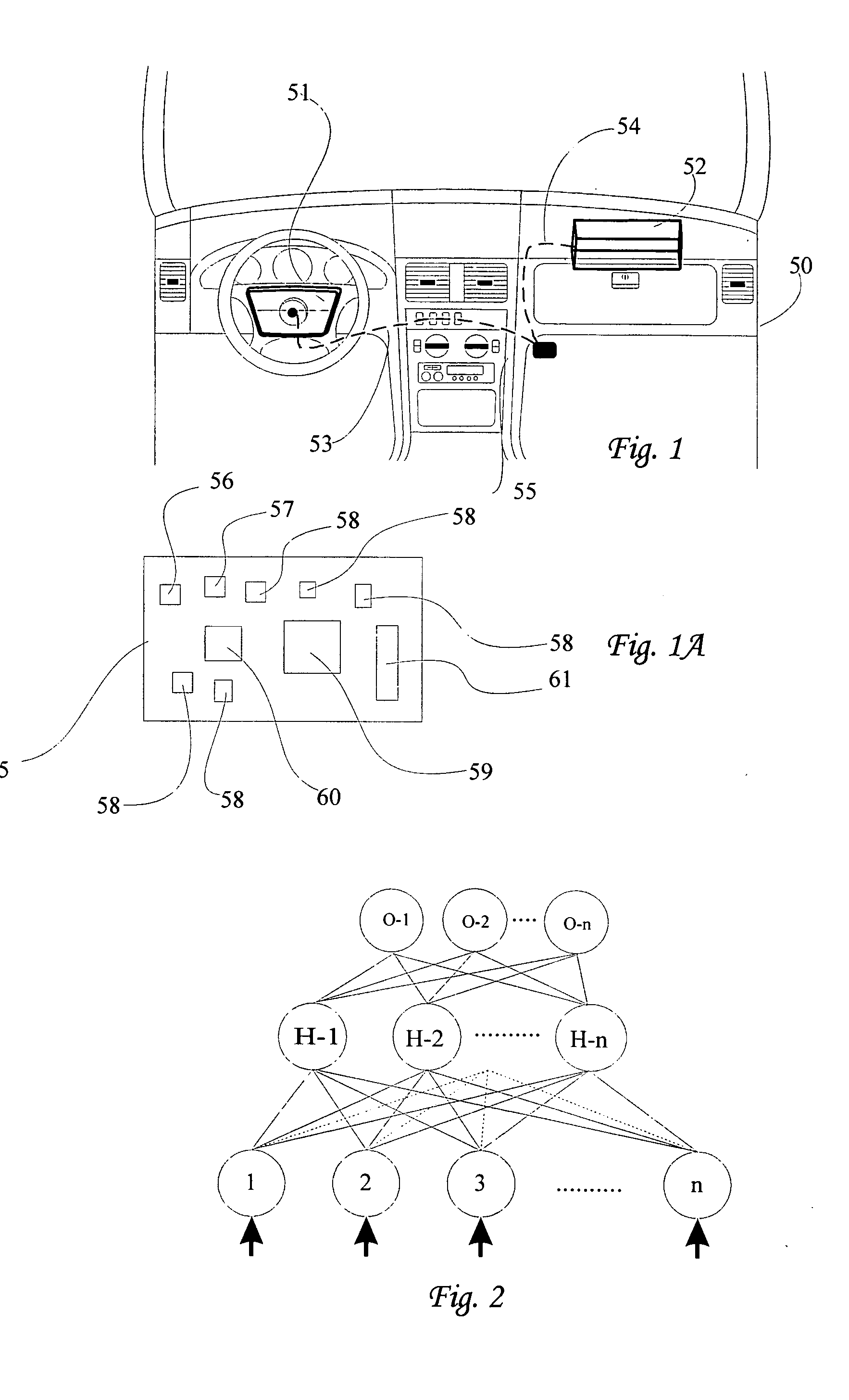
The smart airbag problem is complex and difficult to solve by ordinary mathematical methods.
It is one problem to predict that a crash has a
severity level requiring the deployment of an airbag.
To also simultaneously consider the influence of occupant size, weight, position and / or velocity, renders this problem for all practical purposes unsolvable by conventional methods.

