Method and apparatus for capture and sequester of carbon dioxide and extraction of energy from large land masses during and after extraction of hydrocarbon fuels or contaminants using energy and critical fluids

a carbon dioxide and energy extraction technology, applied in the field of carbon dioxide capture and sequestration and energy extraction, can solve the problems of inability to economically viable, early attempts to process bodies of oil shale in situ by heating kerogen in oil shale, and attempts to process bodies of oil shale above ground, so as to accelerate the catalytic reaction of co2, reduce energy and critical fluid requirements, the effect of increasing volumetric efficiency

Active Publication Date: 2007-11-15
RAYTHEON CO
View PDF23 Cites 145 Cited by
  • Summary
  • Abstract
  • Description
  • Claims
  • Application Information

AI Technical Summary

Benefits of technology

[0040]The objects are further accomplished by providing a system for reducing energy and critical fluid requirements during and after extraction of hydrocarbons comprising means for generating carbon dioxide (CO2) from one of an internal source or external source of methane, means for providing the CO2 as the critical fluid into a well, means for providing a catalyst to the well, means for providing heat energy to the well, means for processing hot fluids, including CO2, methane (CH4), oil, steam/water and vapor from the well, and means for converting the hot fluids into reusable CO2, CH4, electrical energy and water. The well comprises an input borehole and an extraction borehole. The system comprises an input tank opening and an extraction tank opening for an above ground batch or continuous flow plant process. The catalyst comprises sodium hydroxide (NaOH). The system comprises a mixer for combining and introducing the carbon dioxide and the catalyst to the well. The means for providing heat energy to the well comprises means for generating electrical energy. The means for providing heat energy to the well comprises means for providing RF energy. The means for processing hot fluids from the well comprises a heat exchanger coupled to a gas/liquid separator and a steam turbine. The steam turbine drives an electrical generator for providing electric power to a grid or for use in the system. The gas/liquid separator provides liquid oil to a secondary heat exchanger for generating heat through secondary heat r

Problems solved by technology

Early attempts to process bodies of oil shale in situ by heating the kerogen in the oil shale, for example, using RF energy, injecting superheated steam, hot liquids or other materials or by fire flooding into the oil shale formation, have not been economically viable even if fundamentally feasible (which some were not).
Early and current attempts to process bodies of oil shale above ground to obtain the oil and gas in the oil shale, for example, by mining, crushing and heating the shale in a batch or continuous retort furnace, have not been environmentally feasible nor economically viable.
The in situ processes typically leave large amounts of residual energy and residual hydrocarbons in the ground which has unknown effects on the landscape and ecology and can be considered “wasted” energy.
These processes also typically require large amounts of electrical energy which is usually provided by a power plant, either local or remote.
This process has met with limited success and does not purpose to capture or sequester significant amounts of CO2 in the reservoir.
However, this approach by itself requires longer application of RF power and more variation in the power level with time.
While other in situ methods project years of heating by conduction, cracking and vaporization to get oil from shale, using RF energy to heat the shale and the critical fluid for forced convection and extraction reduces the time to production to weeks or months.
In most instances these hydrocarbons are now liberated and mobile and able to migrate toward undesirable areas such as aquifers, causing pollution.
The longer the residual heat remains and the farther reaching it is, the higher the probability of residual oil and gas migration

Method used


Image

  • Method and apparatus for capture and sequester of carbon dioxide and extraction of energy from large land masses during and after extraction of hydrocarbon fuels or contaminants using energy and critical fluids
  • Method and apparatus for capture and sequester of carbon dioxide and extraction of energy from large land masses during and after extraction of hydrocarbon fuels or contaminants using energy and critical fluids
  • Method and apparatus for capture and sequester of carbon dioxide and extraction of energy from large land masses during and after extraction of hydrocarbon fuels or contaminants using energy and critical fluids

Examples


Embodiment Construction

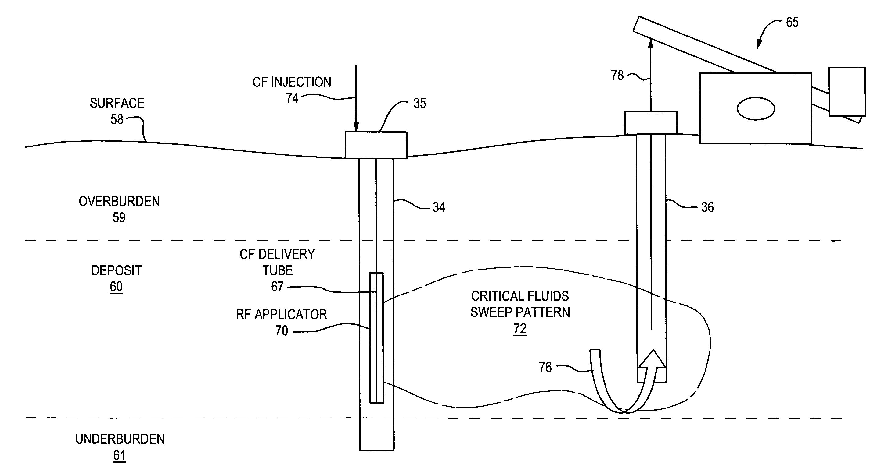
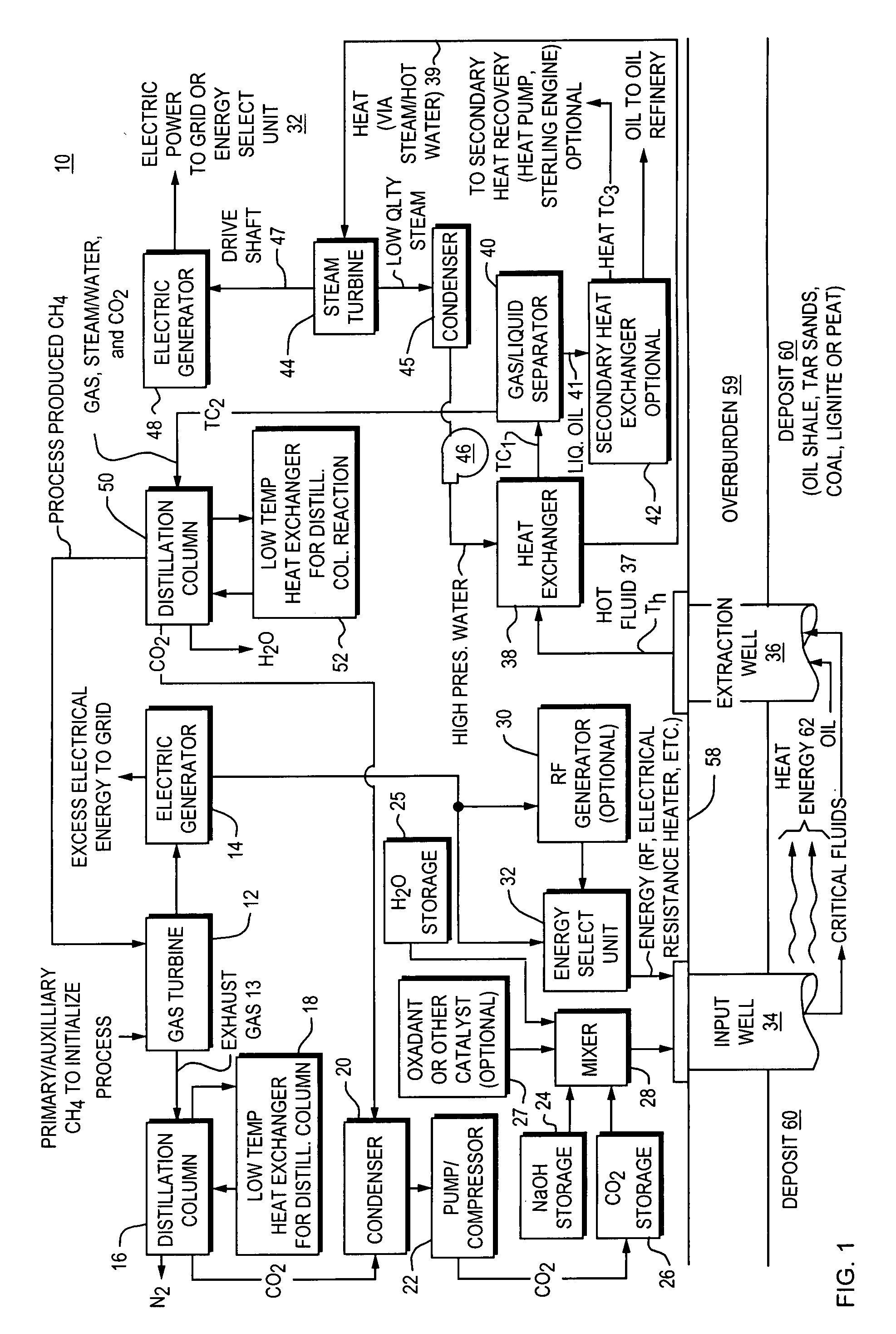
[0048]Referring to FIG. 1, a block diagram of a system 10 is shown for extracting kerogen oil and hydrocarbon gases from oil shale using energy such as electro-magnetic energy from an RF generator and critical fluids such as carbon dioxide (CO2) and reducing greenhouse gases and residual heat in situ during and after the extraction according to the present invention.

[0049]A gas turbine generator 12 receives a natural gas such as methane (CH4) from an outside primary source to initialize the process or internally from the system 10 to operate the gas turbine generator 12 which is connected to an electric generator 14 for generating electricity for internal system 10 use or external uses.

[0050]Any other type of electrical power generator may be substituted, including oil, coal and water powered generation. The gas turbine generator 12 provides exhaust gases which are channeled to a distillation column 16 where Nitrogen (N2) and low pressure carbon dioxide (CO2) are separated out. A lo...


PUM


Abstract

A closed loop system for increasing yield, reducing post process pollution, reducing energy consumed during and after extraction of fuels or contaminants in formations and for sequestering of carbon dioxide C02 from various sources is converted to a critical fluid for use as a flushing and cooling medium. Electrical energy heats a hydrocarbon rich formation resulting in the extraction of hot fluids which are fed to heat exchangers, gas/liquid separator, and steam turbine whereby oil, electric power, carbon dioxide and methane are produced for reuse in the system or for external use. Further, a method for sequestering of carbon dioxide in a formation comprises the steps of injecting CO2 into the reservoir, flushing with cool pressurized CO2 for heat removal, infiltrating with ultra-fine low density suspended catalyst particles of dry sodium hydroxide in CO2, pumping water moistened CO2 into the reservoir to activate the catalysts, binding the CO2 with reacting materials and capping the reservoir.

Description

[0001]This application claims the benefit of Provisional Application No. 60 / 799,090, filed May 10, 2006, which is incorporated herein by reference.BACKGROUND OF THE INVENTION[0002]1. Field of the Invention[0003]This invention relates generally to the reduction of air and land pollution including thermal pollution resulting from the extraction of hydrocarbon fuels from a body of fixed fossil fuels in subsurface formations such as oil shale, and in particular to a method and apparatus for reducing greenhouse gases and residual heat in situ during and after the extraction of oil and gas from oil shale in situ utilizing any extraction process thereof. The invention also is applicable to heavy oil, aging wells, coal, lignite, peat and tar sands and may also be applied above ground in a batch or continuous type process. It may also be applied during and after the extraction of contaminants or residue from a body of fixed earth or from a vessel utilizing electrical energy and critical flui...

Claims


Application Information

Patent Timeline
IPC IPC(8): E21B43/24E21B43/40
CPCE21B41/0064E21B43/164C09K8/594E21B43/40Y02C10/14E21B43/24Y02P90/70Y02A50/20Y02C20/40
Inventor COGLIANDRO, JOHN A.MOSES, JOHN M.
Owner RAYTHEON CO
Why Eureka
Try Eureka