Motion tracking system for real time adaptive imaging and spectroscopy

a motion tracking and adaptive imaging technology, applied in the field of medical imaging, can solve the problems of inability to accurately determine the pose of a patient, the effect of improving the performance of a limited-quality motion sensing means and improving the accuracy of determining the pos

Active Publication Date: 2007-12-06
UNIV OF HAWAII +3
View PDF12 Cites 98 Cited by
  • Summary
  • Abstract
  • Description
  • Claims
  • Application Information

AI Technical Summary

Benefits of technology

[0071] An additional feature of the present invention is that the mirrors and camera can be internally calibrated by analyzing the repeated direct images and the repeated reflected images.
[0089] Another innovation is to incorporate motion filtering and prediction to improve performance of a limited-quality motion sensing means. Motion filtering refers to using information about an object's prior positions to infer its motion and thereby improve accuracy in determining pose (over methods which look only at the most recent position and ignore prior positions).

Problems solved by technology

These types of scans that detect motion inside a patient or other object over time (“digital angiography systems”) can also have a long duration, and be subject to the problem of patient or object motion.
Many tomographic imaging techniques rely on detecting very small percentage changes in a particular type of signal, which makes these techniques even more susceptible to movements.
However, these small signal changes may easily be obscured by signal changes of similar or even greater size that occur during unintentional subject movements.
Because tomographic techniques require that so many images be taken (because so many slices and scanning steps are necessary), the scan has a long duration, so that motion of the subject is a substantial problem for acquiring accurate data.
These strict requirements cannot be met by many subjects in special populations, such as children and infants, very sick patients, subjects who are agitated perhaps due to anxiety or drug use, or patients with movement disorders, resulting in data with motion artifacts.
Similarly, it is exceedingly difficult to perform scans in awake animals.
The basic problem is that it may take several minutes for a scan to be completed, but the patient or other object being scanned cannot remain still for several minutes.
Further, the space for a patient or other object being scanned (the “scanning volume”) in an MR machine is very limited—there is very little space in an MR machine once a patient has been positioned inside for a scan.
While these approaches are particularly useful for reducing artifacts (or imaging errors) due to flowing blood, swallowing or eye movements, they afford little improvement during movements of entire organs, such as head movements.
These techniques can reduce motion sensitivity of MR scans under certain conditions, but cannot eliminate errors from motion under all conditions or for very quick movements.
However, these methods are inherently slow because they use MRI, i.e. they correct movements only every few seconds, and are unable to correct for motion in certain directions (orthogonal to the scan planes; in other words, towards or away from the planes in which the scans are being taken).
While all of these techniques reduce sensitivity to subject motion, several problems remain.
One major problem is related to the manner in which typical tomographic imaging methods acquire data.
For all methods described above, even if motion sensitivity for each individual acquisition (defining a line in k-space) is reduced, these methods typically do not account for variations in head pose amongst the different k-space lines.
Second, the methods poorly tolerate fast movements within individual acquisition steps.
Finally, one of the most significant issues is that none of these techniques can be applied universally across all the various scanning methods (pulse sequences—the order and manner in which slices are imaged) used in MRI or other tomographic scanning techniques.
While these MR-based “adaptive MRI” techniques provide good results in many situations, they intrinsically interfere with MR acquisitions, work only for a limited number of MR sequences, and are limited to measuring the position or pose a few times per second only.
However, SV systems have three limitations for adaptive MR imaging: (1) measurement accuracy decreases as the distance between the cameras becomes smaller, (2) the accuracy of orientation measurement decreases as the target becomes smaller; and (3) SV systems have high sensitivity to-errors in internal calibration, i.e. small errors in the relative position or rotation of the cameras may cause large errors in the measured target pose.
However, accurate calibration has to be performed manually, using a specialized calibration tool or target, is time consuming, and cannot be done while patients are being scanned.
However, this ideal separation is not possible in an MR scanner because the opening to the scanning volume (the volume which can be scanned by the scanner) is relatively narrow, making it impossible to move the cameras sufficiently far apart and still view into the scanning volume.
Additionally, tracking with SV cameras works optimally with larger tracking targets; however, the space in the MR or other scanner environment is very limited.
As noted above, slight errors in the internal calibration of SV systems can produce large measurement errors.
However, the study contains information showing that a tiny 1 / 100th degree change in the camera alignments can produce a 2.0 mm error in the position measurement and the study co-authors privately communicated to the present inventors that maintaining calibration was impracticably difficult.
The prior art has no means to track or correct for these slow changes while the medical imaging system is in service, imaging patients.
The error which accumulates in the co-registration, because of loss of camera calibration, is a severe problem for motion compensation in medical imaging using an external tracking system.
However, since time on a medical imaging system is limited and expensive, removing patients and conducting repeated recalibration with a specialized calibration tool is prohibitively expensive.
While a bite bar may be tolerated by healthy and cooperative volunteers, it is an impractical solution for sick or demented patients, or young children.
Therefore, while stereovision systems are able to track subject motion for use with adaptive imaging techniques when conditions are ideal, the use of SV systems for routine clinical scans proves impractical due to cumbersome recalibration procedures, instabilities over time, and awkward size and attachment of tracking markers (i.e. large marker requiring use of a bite bar).
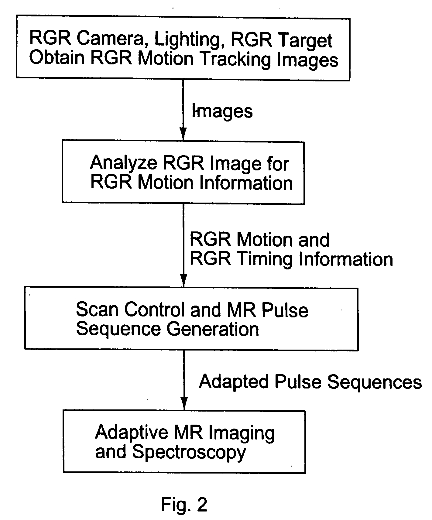
The determination of the subject pose based on actual measurements is an estimation problem.

Method used


Image

  • Motion tracking system for real time adaptive imaging and spectroscopy
  • Motion tracking system for real time adaptive imaging and spectroscopy
  • Motion tracking system for real time adaptive imaging and spectroscopy

Examples


Embodiment Construction

[0103]FIGS. 1 and 2 illustrate the essential elements of the presently preferred embodiments of a system for motion tracking for real-time adaptive imaging and spectroscopy. The best modes are illustrated by way of example using a patient in an MR scanner and RGR object orientation marker, but of course, other objects can be scanned besides patients, other scanners can be used besides MR scanners, and other object orientation markers can be used besides RGRs.

[0104] As shown in FIG. 1, a patient P is imaged in a scanning volume V inside an MR scanner magnet 20. An RGR tag or target 30 is affixed to the patient P near the organ of interest being scanned (e.g., the head). A detector, such as a camera 40 (the “RGR Camera”) outside the scanner magnet 20 observes the RGR target 30, either directly or optionally via one or more mirrors on the wall of the scanner bore or in some other convenient location (not shown). As also shown in FIG. 2, the RGR Camera 40 is connected to the RGR Proces...


PUM


Abstract

Current MRI technologies require subjects to remain largely motionless for achieving high quality magnetic resonance (MR) scans, typically for 5-10 minutes at a time. However, lying absolutely still inside the tight MR imager (MRI) tunnel is a difficult task, especially for children, very sick patients, or the mentally ill. Even motion ranging less than 1 mm or 1 degree can corrupt a scan. This invention involves a system that adaptively compensates for subject motion in real-time. An object orientation marker, preferably a retro-grate reflector (RGR), is placed on a patients' head or other body organ of interest during MRI. The RGR makes it possible to measure the six degrees of freedom (x, y, and z-translations, and pitch, yaw, and roll), or “pose”, required to track the organ of interest. A camera-based tracking system observes the marker and continuously extracts its pose. The pose from the tracking system is sent to the MR scanner via an interface, allowing for continuous correction of scan planes and position in real-time. The RGR-based motion correction system has significant advantages over other approaches, including faster tracking speed, better stability, automatic calibration, lack of interference with the MR measurement process, improved ease of use, and long-term stability. RGR-based motion tracking can also be used to correct for motion from awake animals, or in conjunction with other in vivo imaging techniques, such as computer tomography, positron emission tomography (PET), etc.

Description

[0001] This application claims priority to US provisional patent application 60 / 802,216 filed May 19, 2006, incorporated herein by reference.TECHNICAL FIELD [0002] This invention relates generally to the field of medical imaging, and more specifically to a system for correcting defects in medical images that are caused by a patient's movement during long duration in vivo (in the living body) scans, such as magnetic resonance scans. BACKGROUND ART [0003]“Tomographic” imaging techniques make images of multiple slices of an object. Multiple tomographic images can then be aligned and assembled using a computer to provide a three dimensional view. Some commonly used tomographic imaging techniques include magnetic resonance imaging (MRI) and magnetic resonance spectroscopy (MRS) techniques, which are ideal for assessing the structure, physiology, chemistry and function of the human brain and other organs, in vivo. Because the object of interest is often imaged in many slices and scanning ...

Claims


Application Information

Patent Timeline
Patent Type & Authority Applications(United States)
IPC IPC(8): G01P13/00G06K9/00
CPCA61B5/055A61B5/1127A61B5/721A61B5/7292G01R33/28G06K2009/3291G06T7/0012G06T7/004G06K2017/0045A61B6/0492G01R33/56509G06T7/70G06V10/62A61B5/1128A61B6/547H04N7/18A61B5/0077
Inventor ERNST, THOMAS MICHAELPRIETO, THOMAS EDMUNDARMSTRONG, BRIAN STEWART RANDALL
Owner UNIV OF HAWAII
Why Eureka
Try Eureka