Time-resolved fluorescence spectrometer for multiple-species analysis

a fluorescence spectrometer and multiple-species technology, applied in the field of time-resolved fluorescence spectrometers, can solve the problems of limiting the application of strong-emitting targets, requiring expensive and delicate equipment, and complicating the cross-talk between the pump light and the stokes signal at the detection level

Inactive Publication Date: 2008-05-22
OPTICAL ONCOLOGY
View PDF19 Cites 61 Cited by
  • Summary
  • Abstract
  • Description
  • Claims
  • Application Information

AI Technical Summary

Benefits of technology

[0013]In accordance with the present invention a device such as a RadiaLight® switch is used for the implementation of a TRF instrument that has the quality of being compact, rugged and fast (with measurement times of less than 1 s). The instrument can perform single and multiple species (10 to 25) analysis, with the capability of measuring fluorescence intensity and / or lifetime decay.
[0014]An embodiment of the system uses the RadiaLight® switch as a time-division multiplexing device that delivers a pulsed fluorescent pump light sequentially into one or more samples. At the same time, the RadiaLight® device collects the fluorescence produced by each sample in a synchronized sequence of pulses, thus providing a precise temporal profile of the fluorescence signal induced by the pump pulse. By using long lifetime-decay fluorophores, the device can perform TRF spectroscopy within the period of one or a few cycles of the RadiaLight® switch. To achieve this, transition metal complexes (TMCs, also known as Metal-Ligand-Complexes, MLC's) such as [Ru(Ph2phen)3]Cl2, can be used as the fluorophores. These fluorophores have the property of long excited state lifetimes (0.1->5 μs), high quantum yields (0.04-0.5), and strong ultraviolet-visible (UV-visible) absorption. (see J. N. Demas, B. A. DeGraff; “On the Design of Luminescence Based Temperature Sensors”, SPIE Proceedings Vol. 1796, 71-75 (1992); H. M. Rowe, W. Xu, J. N. Demas, B. A. DeGraff; “Metal Ion Sensors Based on a Luminescent Ruthenium (II) Complex: The Role of Polymer Support in Sensing Properties”, Appl. Spectrosc. 56(2) 167-173 (2002); L. Sacksteder, M. Lee, J. N. Demas, B. A. DeGraff; “Long-Lived, Highly Luminescent Rhenium(I) Complexes as Molecular Probes: Intra- and Intermolecular Excited-State Interactions”, J. Am. Chem. Soc. 115, 8230-8238 (1993); and T. Harri Takalo, K. Veli-Matti. Mukkala; “Luminescent Lanthanide Chelates”, U.S. Pat. No. 5,571,897, Nov. 5 (1996)). Luminescent lifetimes as long as 100's of μs have been measured for Lanthanide complexes. (See U.S. Pat. No. 5,571,897). The lifetimes of these TMCs fall precisely within the range of time-resolution capabilities of the RadiaLight® switch. In this embodiment, the device can perform TRF of a sample with a plurality of components, each of them associated with a fluorophore that has a distinct decay time that lies within the time range detectable by the device.
[0015]Another embodiment of the invention combines the time-division multiplexing capability of the device with the ability to use a plurality of optical band-pass filters for each optical channel. This embodiment enhances the multiplicity of components that the invention can analyze simultaneously, by using fluorophores that have different lifetimes and different emission spectra.

Problems solved by technology

Also, contrary to Raman scattering, typical Stokes shifts for fluorescence phenomena are a few 10's of nm apart from the pump light, which complicates the cross-talk between the pump light and the Stokes signals at the detection level.
Intrinsic fluorescence uses the fluorescence emission of the target molecules themselves, which limits its application to strongly emitting targets.
1) Short lifetime measurement techniques require the use of expensive and delicate equipment: pulsed pump lasers and state-of-the-art synchronized photo-detection schemes.
2) Fluorescence spectroscopy instrumentation is bulky.
3) Conventional fluorescence techniques require the use of high performance optical filters. This adds on to the price of the instrument, its complexity, and reduces the signal collection efficiency. It also increases the cross-talk between pump and Stokes signals, and between the Stokes signals from different fluorophores.
4) Due to the extra complexity and cross-talk added by the optical filtering procedures, only small number of target substances can be analyzed simultaneously (3 or 4 at a time).
5) In fluorescence lifetime measurements, fluorophore concentration values are normally disregarded, as the measurement technique is only involved with relative changes of the signal in time. Also, the analytical complexity of deriving both lifetime and concentration values increases rapidly with the number of targets being analyzed. As a result, current lifetime fluorescent techniques are limited to fixed concentration measurements for a few target substances (2, 3 or 4).
6) Due to the close spectral proximity between the pump and Stokes signals in fluorescence spectra, and between Stokes signals from different fluorophores, high-performance optical filtering techniques are required. This increases cost and complexity of typical fluorescence devices.

Method used


Image

  • Time-resolved fluorescence spectrometer for multiple-species analysis
  • Time-resolved fluorescence spectrometer for multiple-species analysis
  • Time-resolved fluorescence spectrometer for multiple-species analysis

Examples


Embodiment Construction

[0056]The following detailed description is meant to be illustrative only and not limiting. Other embodiments of this invention will be obvious to those skilled in the art in view of this description.

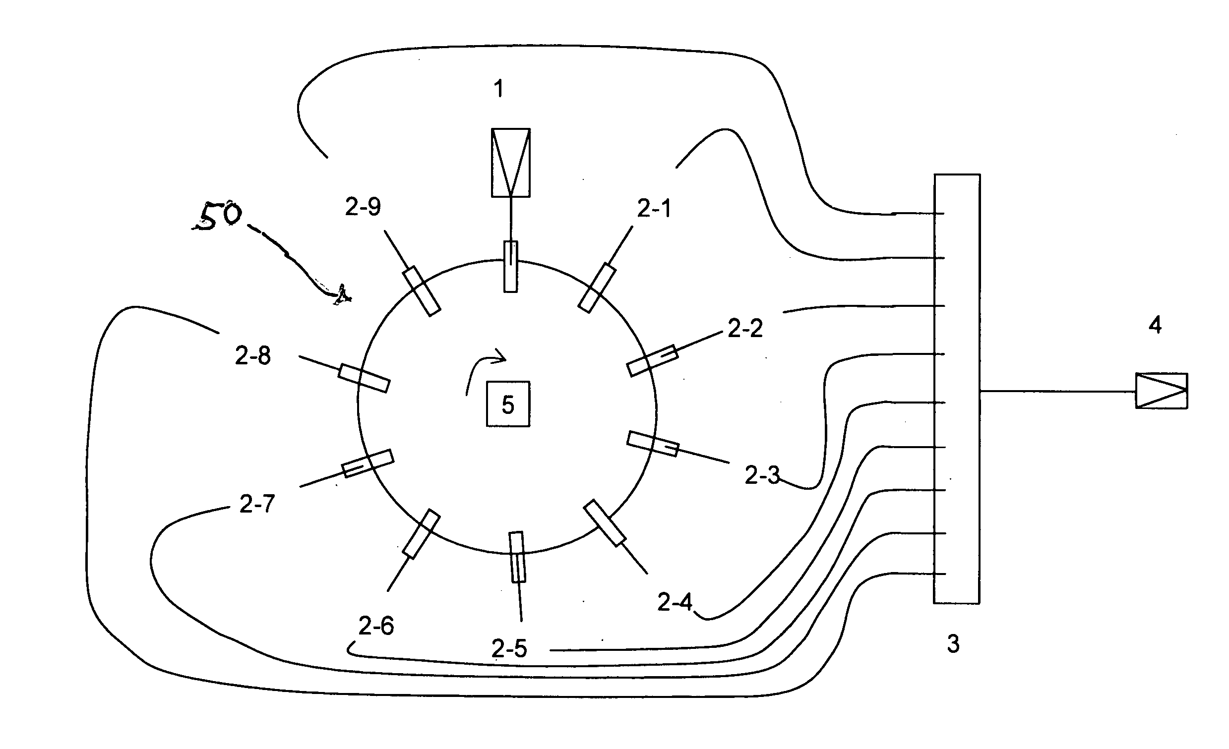
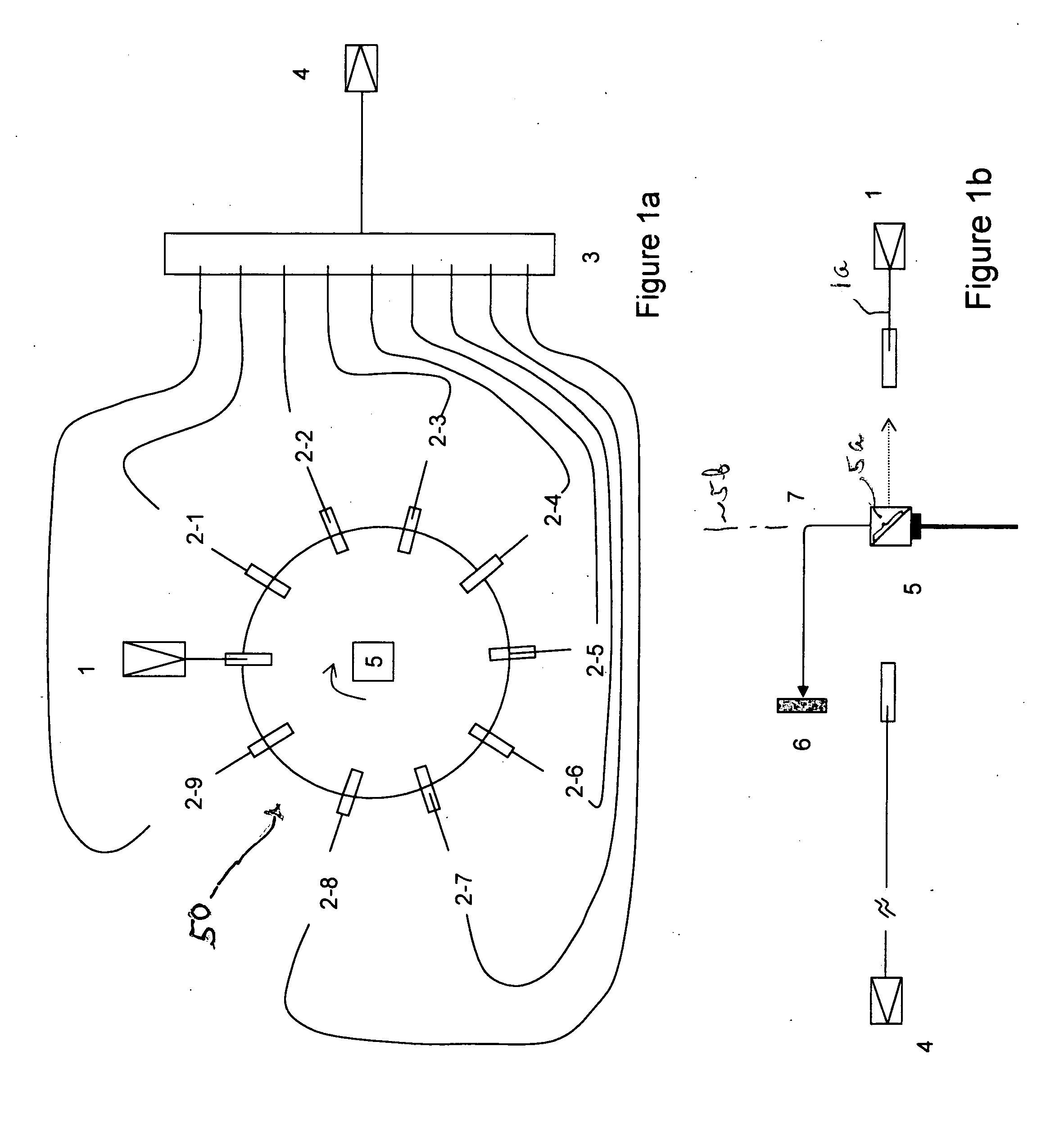
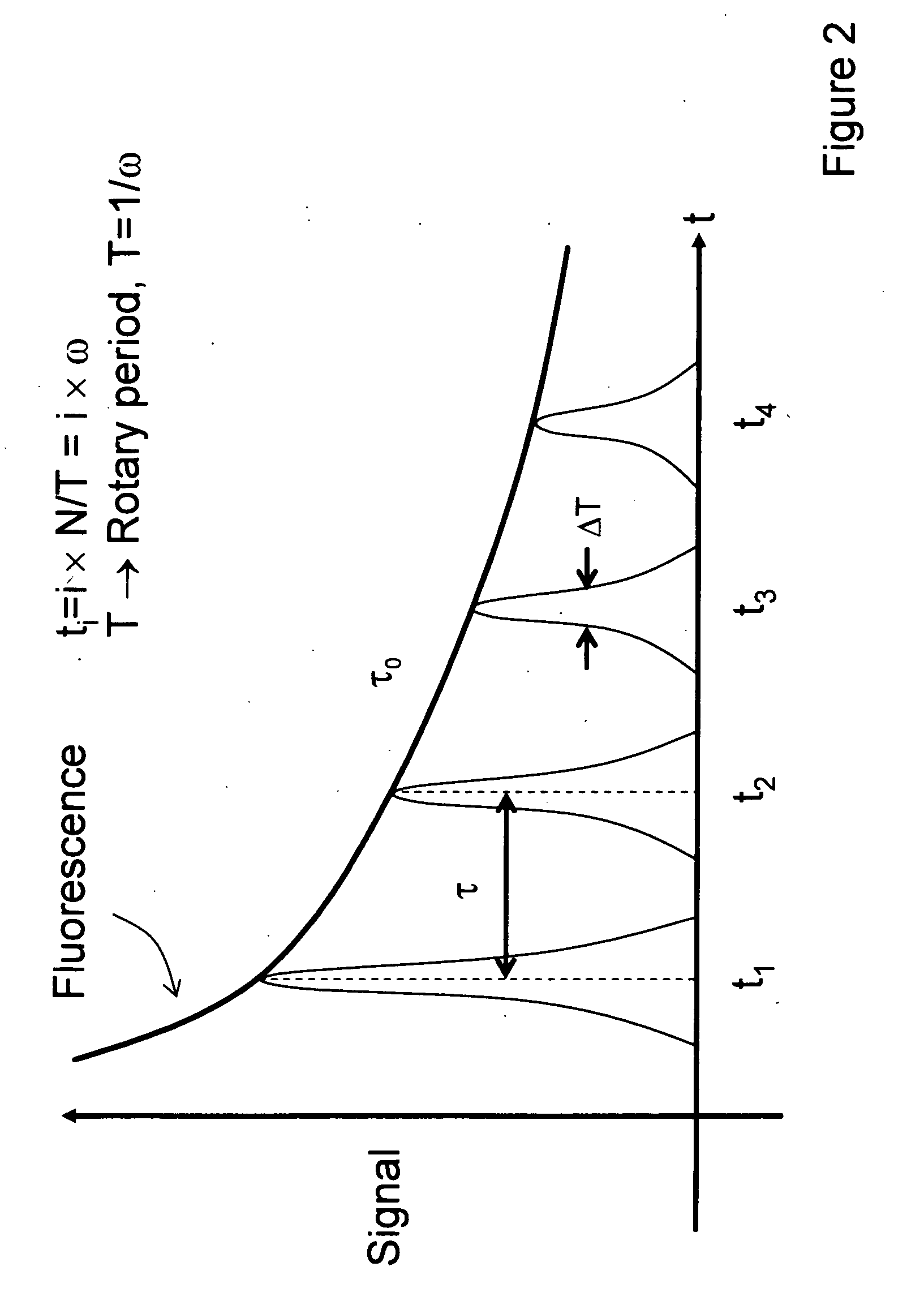
[0057]In accordance with this invention a time-resolved, fluorescence spectrometry device architecture is provided that combines a high-speed time-division optical sampling engine with a unique data processing algorithm, discrete Principal Component Analysis (dPCA), in order to produce time-resolved, accurate fluorescence measurements with low signal levels. A variety of specific embodiments can be provided to implement the invention. The invention significantly decreases the sample processing time, while increasing the number of material samples that can be processed at one time. This invention also improves the environmental ruggedness of the device while significantly reducing the implementation cost.

[0058]Referring to FIGS. 1a and 1b, one embodiment of this invention employs a rotar...


PUM

PropertyMeasurementUnit
fluorescent lifetimesaaaaaaaaaa
timeaaaaaaaaaa
time resolutionaaaaaaaaaa

Abstract

A time-resolved, fluorescence spectrometer makes use of a RadiaLight® optical switch and no dispersive optical elements (DOE) like gratings. The structure is unique in its compactness and simplicity of operation. In one embodiment, the spectrometer makes use of only one photo-detector and an efficient linear regression algorithm. The structure offers a time resolution, for multiple species measurements, of less than 1 s. The structure can also be used to perform fluorescence correlation spectroscopy and fluorescence cross-correlation spectroscopy.

Description

FIELD OF THE INVENTION[0001]This invention relates to a time-resolved fluorescence spectrometer that is capable of measuring samples with multiple components simultaneously. The instrument is environmentally rugged, has low cost, and can be used in field applications where other fluorescence techniques could not be implemented.BACKGROUND OF THE INVENTION[0002]Fluorescence spectroscopy is a widely used technique in the Biological sciences. In fluorescence spectroscopy, light at a specific frequency is absorbed by a given molecule or fluorescent entity (also called fluorophore), exciting its electronic state. The fluorescent entity then emits light at a slightly different frequency, as the fluorophore returns to the original ground state. Fluorescence spectroscopy is analogous to Raman spectroscopy in that a pump light excitation induces the emission of Stokes light, shifted to a lower frequency relative to the pump light. However, fluorescence requires the absorption of the pump ligh...

Claims


Application Information

Patent Timeline
Patent Type & Authority Applications(United States)
IPC IPC(8): G01N21/64
CPCG01J3/02G01J3/0218G01J3/0256G01N21/6408G01J3/2889G01J3/4406G01J3/10
Inventor CLAPS, RICARDOSMITH, BRADLEY A.
Owner OPTICAL ONCOLOGY
Why Eureka
Try Eureka