Method And Device For Preparing Powder On Which Nano Metal, Alloy, And Ceramic Particles Are Uniformly Vacuum-Deposited

a technology of nano metals and ceramic particles, applied in the field of powder preparation, can solve the problems of several work processes or limit materials used in the preparation of nano particles, non-uniform size, and conventional nano-particle preparation methods, and achieve the effects of maximizing the nano effect, high purity, and excellent size uniformity

Inactive Publication Date: 2008-10-16
P & I
View PDF3 Cites 16 Cited by
  • Summary
  • Abstract
  • Description
  • Claims
  • Application Information

AI Technical Summary

Benefits of technology

[0011]The present invention provides a device and a technology for preparing nano metal, alloy, and ceramic particles that are excellent in size uniformity, on a surface of a powder type base, using a vacuum deposition method. The present invention has an advantage that a high purity is obtained by using a vacuum deposition method, and no observation of a general cohesion phenomenon is made among the nano particles by performing a nano deposition on powder basis, thereby maximizing a nano effect. Various vacuum deposition methods can be used, and most materials such as metal, alloy, and ceramic can be formed as the nano particles. A production process can be highly simplified owing to the absence of chemical processing. By adjusting independently controllable process variables such as a sputtering power, a vacuum degree, and an agitation speed, a product having an excellent reproducibility can be prepared. In addition to a functionality of the existing powder base, a functionality of the nano particle is added, thereby making it possible to prepare multi-function powder. This is expected to be variously applicable to energy conversion field, fuel cell, and nitrogen compound decomposition-purposed catalyst fields, as well as daily commodities, wastewater processing, and optical catalyst fields requiring the anti-bacteria and sterilization.

Problems solved by technology

However, the conventional nano-particles preparing methods have a drawback that they require several work processes or limit material for preparing the nano particles, respectively.
In the nano particles prepared by the conventional method, coalescence between them easily occurs, thereby making a size non-uniform.
In case where an additive such as a surfactant or a dispersant is used for preventing it, there occurs a drawback that the prepared nano particles contain a large amount of impurities, thereby deteriorating the nano particles in purity.
However, this method is not suitable to a mass production of the nano particles, and is very difficult to control the nano particles in size and uniformity.
However, the conventional method has a disadvantage that the nano particles are not uniform in size and are discontinuously formed over a whole of the powder.
Also, the conventional method has a drawback that the separation of the deposition and mixing steps causes a complex preparation process and an increase of a preparation time, and it is difficult to increase contents of the nano particles, and it is not easy for mass production.
Thus, in the powder having the nano particles earlier formed, as the deposition time increases, coalescence between them is caused, and the nano particles increase at a micro size or more and lose a nano characteristic.
Thus, the deposition time is limited to before the occurrence of the coalescence, thereby causing a problem in increasing the contents of the nano particles to the extent required for application.
This cause results in a drawback that, in a conventional agitator of FIG. 2 being of a flat bottom type not a present barrel type and agitating the powder on a plane, when agitation is performed, not being perfectly hidden, the powder already exposed to a deposition zone before the agitation is again exposed to the deposition zone.

Method used


Image

  • Method And Device For Preparing Powder On Which Nano Metal, Alloy, And Ceramic Particles Are Uniformly Vacuum-Deposited
  • Method And Device For Preparing Powder On Which Nano Metal, Alloy, And Ceramic Particles Are Uniformly Vacuum-Deposited
  • Method And Device For Preparing Powder On Which Nano Metal, Alloy, And Ceramic Particles Are Uniformly Vacuum-Deposited

Examples


first embodiment

Nano Silver Deposition on Salt and Sugar

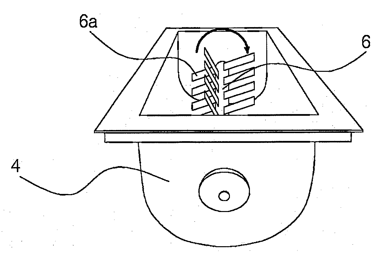
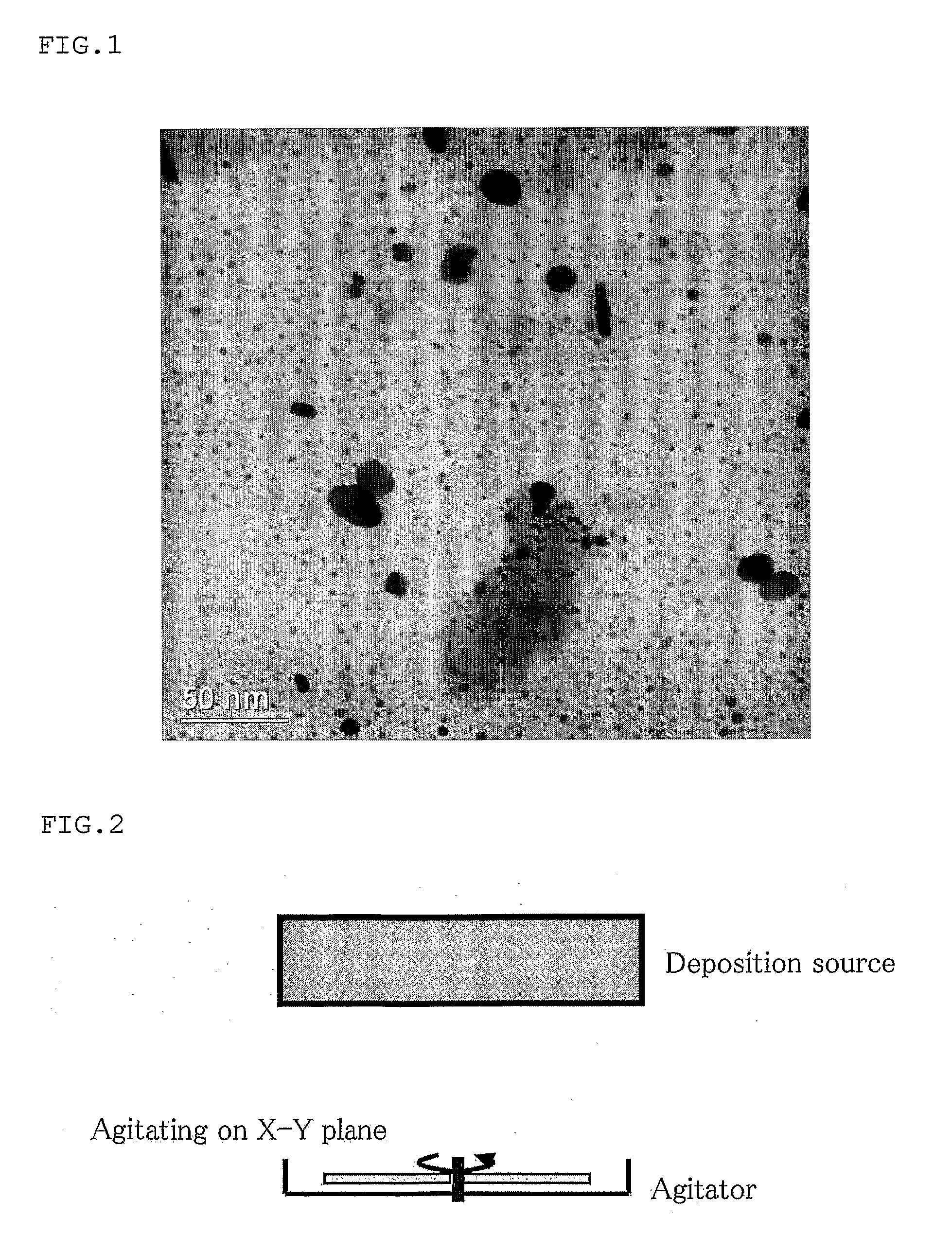
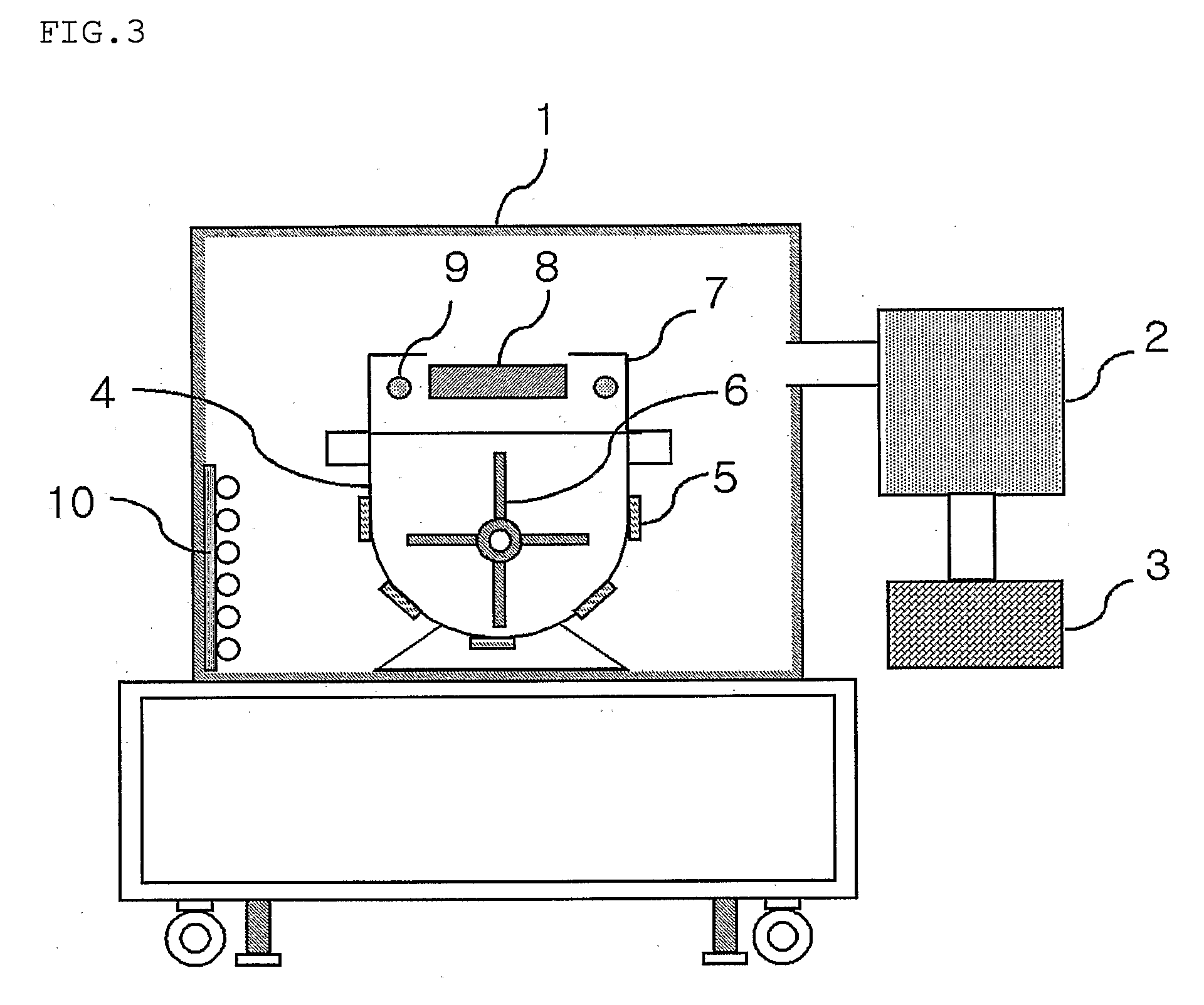
[0038]About 25 kg of dried salt or sugar was put in the barrel 4 of FIG. 3, and a silver target was mounted on a DC magnetron sputter. After the powder was loaded in the vacuum chamber 1, a vacuum state was formed using the vacuum pump. A degree of vacuum is provided by only the low vacuum pump 3 or in combination with the high vacuum pump 2, depending on a work condition. An initial vacuum is kept in about 10−1 to 10−6 torr. Sputtering gas employs argon (Ar) gas. An injection amount of argon gas can vary depending on the work condition. In general, injection is performed to keep a vacuum of about 10−1 to 10−4 torr. After pumping to a desired vacuum degree and sputtering gas injection, silver target sputtering is performed, rotating the impeller 6 within the barrel 4. A rotation speed of the impeller 6 is controllable, and a sputtering speed is controllable depending on applied power and is generally within and out of a range of 1 W / cm2 to 200...

second embodiment

Nano Silver Deposition on Activated Charcoal

[0040]About 20 kg of activated charcoal was provided in a barrel within a vacuum chamber, and silver nano particles were deposited on the activated charcoal using the same device and work condition as those of the first embodiment. If materials having a difficulty in obtaining the desired vacuum degree, a porous material such as the activated charcoal, perform the vacuum pumping, being heated by a heater installed over the barrel, they can easily perform the vacuum pumping within a little more fast time. Silver contents of the activated charcoal are controllable by varying a work condition such as a sputtering power, a sputtering time, an impeller rotation speed, and a vacuum degree, and are controllable within a range of 10 ppm to 1000 ppm. This can be used for an anti-bacteria and sterilization filter for a water purifier.

third embodiment

Nano Silver Deposition on Sand

[0041]About 20 kg of sands were provided in a barrel 4 within a vacuum chamber 1, and nano silver particles were deposited on the sands using the same device and work condition as those of the first embodiment. In many cases, the sands generally contain much moisture. Thus, it is good to remove moisture from the sands using a dry process before providing the sands in the barrel 4 within the vacuum chamber 1. Moisture remaining even after the dry process is removed using a heater installed over the barrel 4, and a cold trap 10 within the vacuum chamber 1. The cold trap 10 can trap the moisture within the vacuum chamber 1 using a cold refrigerant and thus, can perform the vacuum pumping with a little more quickness. The silver contents of the sands are controllable by varying a work condition such as a sputtering power, a sputtering time, an impeller rotation speed, and a vacuum degree, and are controllable within a range of 10 ppm to 1000 ppm. This can b...


PUM

PropertyMeasurementUnit
diameteraaaaaaaaaa
particle sizeaaaaaaaaaa

Abstract

The present invention relates to a method and device for preparing powder by depositing nano metal, alloy, ceramic particles that are excellent in size uniformity, on a surface of the powder that is a base, using a vacuum deposition method. In particular, the present invention provides a method and device for preparing the powder on which the nano metal, alloy, and ceramic particles of a very uniform size are deposited, by simultaneously performing deposition and agitation using an effective agitation means for solving a disadvantage of a conventional method where deposition and agitation are separately performed. Also, the present invention provides a method and device for preparing the powder on which nano particles are deposited, in which a nano characteristic is kept by preventing a coalescence phenomenon of nano particles even when a deposition time for increasing contents of the nano particles increases in their preparation.

Description

TECHNICAL FIELD[0001]The present invention relates to a method and device for preparing powder by uniformly vacuum-depositing nano metal, alloy, and ceramic particles on a surface of the powder that is a base, using a vacuum deposition method, and more particularly, to a method and device for preparing powder on which nano particles are deposited, by uniformly forming the nano particles on a surface of the powder basis using physical and chemical vacuum deposition methods.BACKGROUND ART[0002]As particles get small by a nano size (100 nm or less), nano particles have new mechanical, chemical, electric, magnetic, and optical properties different from those of existing micrometer-unit particles. This is a phenomenon appearing as a ratio of surface area to unit volume increases to an extreme. A new application field, which could not be obtained by the existing micrometer-size particles, is being steadily developed using such a quantum size effect, and its academic and technological conc...

Claims


Application Information

Patent Timeline
Patent Type & Authority Applications(United States)
IPC IPC(8): C23C16/44B22F1/054
CPCB01J21/08B01J23/06B01J23/10B01J23/22B01J23/30B01J23/34B01J23/42B01J23/44B01J23/462B01J23/52B01J23/755B01J35/0013B01J37/0221B22F1/0018B22F9/14B22F2998/00B22F2998/10B82Y30/00C02F1/281C02F1/283C02F1/288C02F1/50C04B35/6281C04B35/62815C04B35/62842C04B35/62884C04B35/62892C04B2235/3217C04B2235/3232C04B2235/3244C04B2235/3272C04B2235/3418C23C14/223C23C16/4417B22F2201/11B22F2201/20B22F1/007B22F2202/01B22F1/054B22F1/105B82B3/00B82Y40/00
Inventor KOH, SEOK KEUNBEAG, YOUNG WHOANCHO, JUN SIKJOO, JAE HOHAN, YOUNG GUNLEE, JUNG HWANYO, UN JUNG
Owner P & I
Why Eureka
Try Eureka