Antireflection film, polarizing plate, and image display device

Inactive Publication Date: 2009-03-26
FUJIFILM CORP
View PDF2 Cites 15 Cited by
  • Summary
  • Abstract
  • Description
  • Claims
  • Application Information

AI Technical Summary

Benefits of technology

[0010]An object of the invention is to provide an antireflection film having a sufficient antireflection property and having improved scratch resista

Problems solved by technology

However, these are problematic in that the film strength and the interfacial adhesiveness may lower and the film scratch resistance tends to lower, and therefore, it is a difficult problem to satisfy both low refractivity and high scratch resistance.
However, this has significant limitations in that (1) curing the films requires long-time heating and the production load is therefore great, and (2) the films are not resistant to saponification solution (alkali-processing solution), and therefore in TAC surface saponification, the saponification treatment could not be attained after the formation of an antireflection film.
The method may be effective in some degr

Method used


Image

  • Antireflection film, polarizing plate, and image display device
  • Antireflection film, polarizing plate, and image display device
  • Antireflection film, polarizing plate, and image display device

Examples


Example

Example 1

Preparation of Coating Liquids (Ln-1 to Ln-20) for Low-Refractivity Layer

[0377]The components shown in Table 3 below were mixed, and diluted with cyclohexane and methyl ethyl ketone in a ratio of 10 / 90 of cyclohexane / methyl ethyl ketone so that the resulting mixture could have an overall solid concentration of 5% by mass, thereby preparing coating liquids (Ln-1 to Ln-20).

[0378]In the Table, the parenthesized numeral indicates the amount of the component in terms of part by mass. IRG907 is a radical polymerization initiator, Ciba-Geigy's Irgacure 907 (trade name).

TABLE 3Composition of Coating Liquid for Forming Low refractivity LayerDispersion ofInorganicCoating LiquidFluoropolymerParticlesSolInitiatorLn1 (the invention)P-3 (95)—sol (a) (5)IRG907 (3)Ln2 (the invention)P-4 (95)—sol (a) (5)IRG907 (3)Ln3 (the invention)P-5 (95)—sol (a) (5)IRG907 (3)Ln4 (comparative example)a-2 (95)—sol (a) (5)IRG907 (3)Ln5 (comparative example)a-3 (95)—sol (a) (5)IRG907 (3)Ln6 (the invention)P-...

Example

Example 2

Preparation of Coating Liquids (Ln401 to 409) for Forming Low Refractivity Layer

[0429]Coating liquids (Ln401 to 409) were prepared by mixing each ingredient shown in Table 7 below and diluting the mixture with cyclohexane and methyl ethyl ketone in such a manner that the solid concentration of the entire coating liquid is 5% by mass and the ratio of cyclohexane to methyl ethyl ketone is 10:90.

TABLE 7Inorganic FineParticlePolyfunctionalCoating LiquidFluoropolymerDispersionSolAcrylateInitiatorLn401 (The Invention)P-2 (90)—Sol a (5)DPHA (5)IRG 369 (3)Ln402 (The Invention)P-2 (85)MEK-ST-L (5)Sol a (5)DPHA (5)IRG 369 (3)Ln403 (The Invention)P-2 (85)MEK-ST (5)Sol a (5)DPHA (5)IRG 369 (3)Ln404 (The Invention)P-2 (51)A-2 (39)Sol a (5)DPHA (5)IRG 369 (3)Ln405 (The Invention)P-2 (46)A-2 (39)Sol a (5)DPHA (5)IRG 369 (3)MEK-ST-L (5)Ln406 (The Invention)P-2 (51)A-2 (39)Sol a (5)DPHA (5)IRG 184 (3)Ln407 (The Invention)P-2 (51)A-2 (39)Sol a (5)DPHA (5)IRG 907 (3)Ln408 (The Invention)P-2 (...


PUM

PropertyMeasurementUnit
Fractionaaaaaaaaaa
Fractionaaaaaaaaaa
Volumeaaaaaaaaaa

Abstract

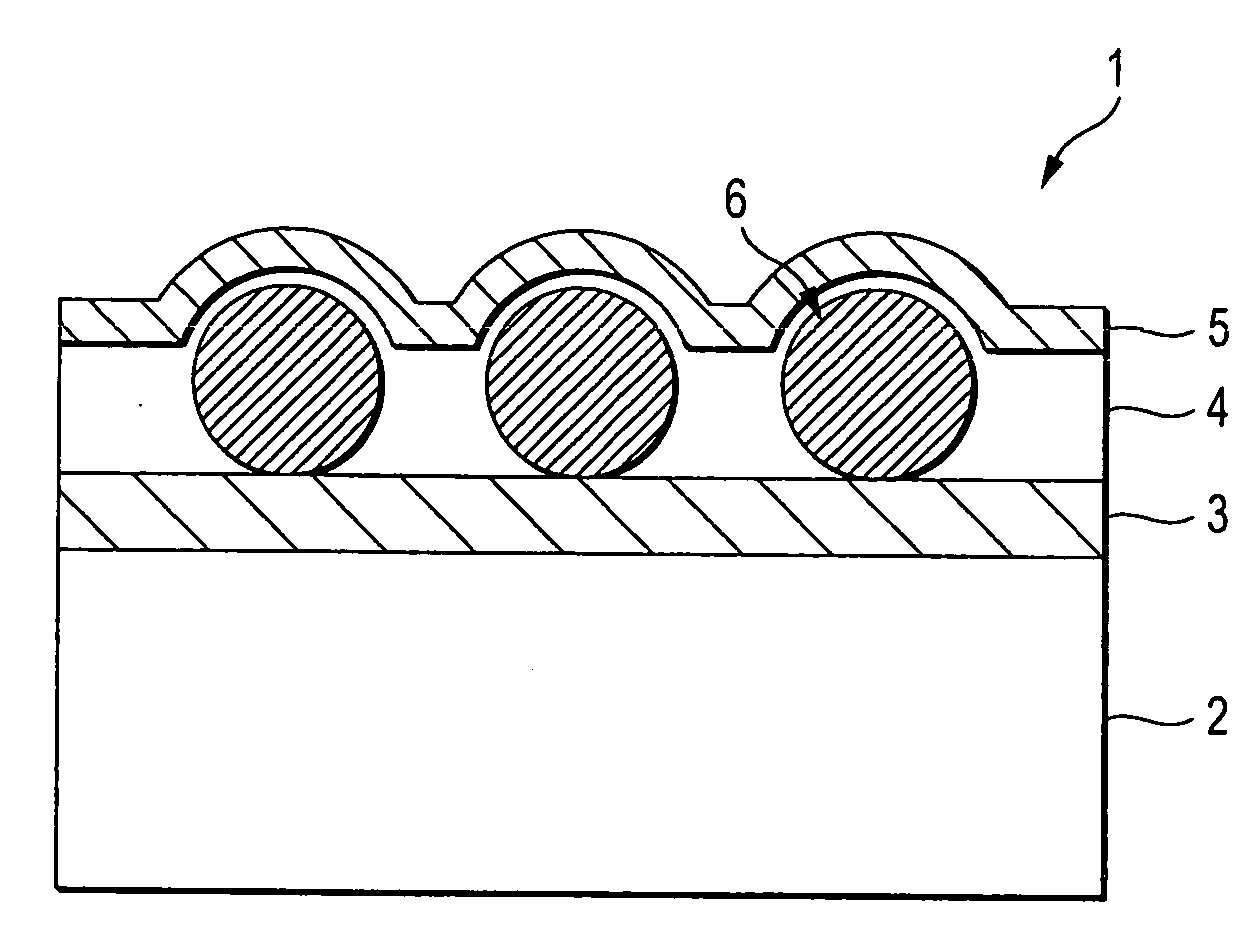
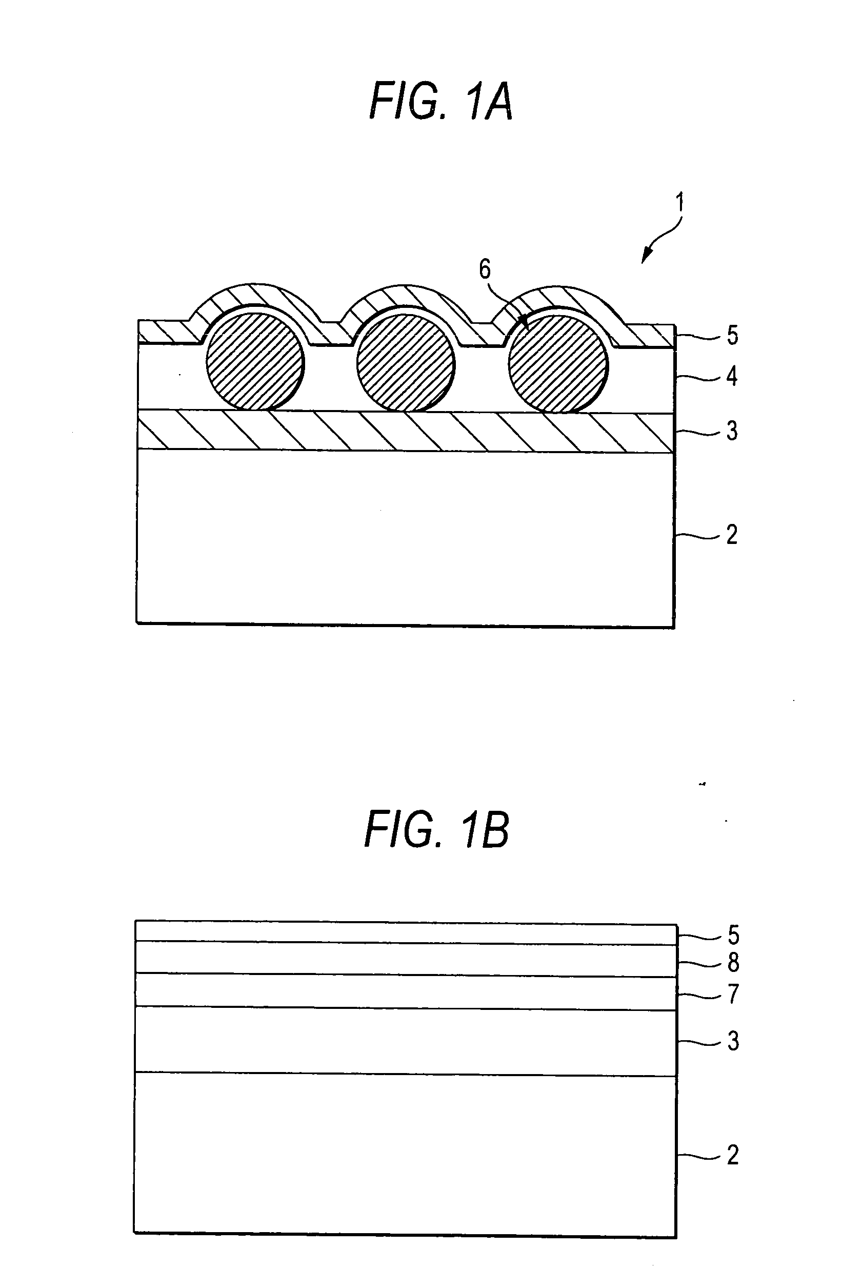
An antireflection film comprising a transparent support and a low-refractivity layer as an outermost layer, the low-refractivity layer being formed by a specific fluoropolymer-containing composition, and a polarizing plate and an image display device comprising the antireflection film.

Description

TECHNICAL FIELD[0001]The present invention relates to an antireflection film, a polarizing plate comprising the antireflection film, and an image display device.BACKGROUND ART[0002]In general, an antireflection film is disposed on the outermost surface of image display devices such as cathode-ray tube (CRT) display devices, plasma display panels (PDP), electroluminescent display devices (ELD) and liquid-crystal display devices (LCD). This is for preventing contrast reduction or image reflection caused by external light reflection on the displays, by reducing the reflectivity owing to the principle of optical interference thereon.[0003]The antireflection film of the type is generally produced by forming, on a support, a low-refractivity layer having a suitable thickness and having a refractivity lower than that of the support. For realizing its low refractivity, the material for the low-refractivity layer is desired to have a refractivity as low as possible. Since the antireflection ...

Claims


Application Information

Patent Timeline
IPC IPC(8): G02B1/11B32B7/02C08F290/06C08L27/12
CPCB32B27/08Y10T428/2495C08F259/08C08F283/12C08F290/06C08F290/062C08F290/14C08F290/142C08K7/26C08L51/003C08L51/085C08L53/00C09D127/12C09D151/003C09D151/085C09D153/00G02B1/11G02B1/111C08F214/18C08L2666/02
Inventor IRITA, KIYOSHINORO, MASAKIYONEYAMA, HIROYUKI
Owner FUJIFILM CORP
Why Eureka
Try Eureka