Foam sheet and production process thereof

a technology of foam sheet and production process, which is applied in the field of foam sheet, can solve the problems of insufficient durability and crack resistance, inability to produce thin foam sheets using conventional forming processes, and formation of internal defects in the material itself, and achieves the effects of high reflection efficiency, convenient production, and satisfactory workability

Inactive Publication Date: 2009-05-21
OJI HLDG CORP
View PDF14 Cites 6 Cited by
  • Summary
  • Abstract
  • Description
  • Claims
  • Application Information

AI Technical Summary

Benefits of technology

[0028]The present invention provides a foam sheet that has microcells and can easily be made to be thin and have multiple layers, and a production process thereof. In addition, the present invention allows the production of a light reflector that has microcells, is thin and has high reflection efficiency as well as satisfactory workability, productivity and formability.

Problems solved by technology
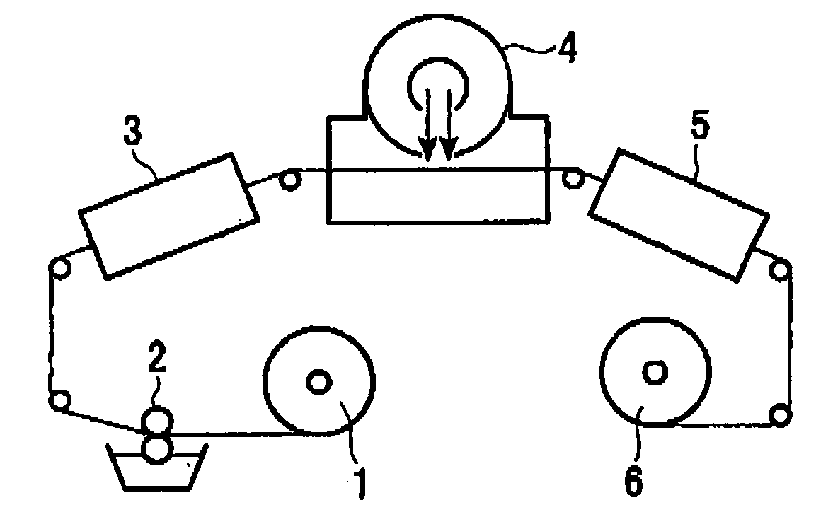
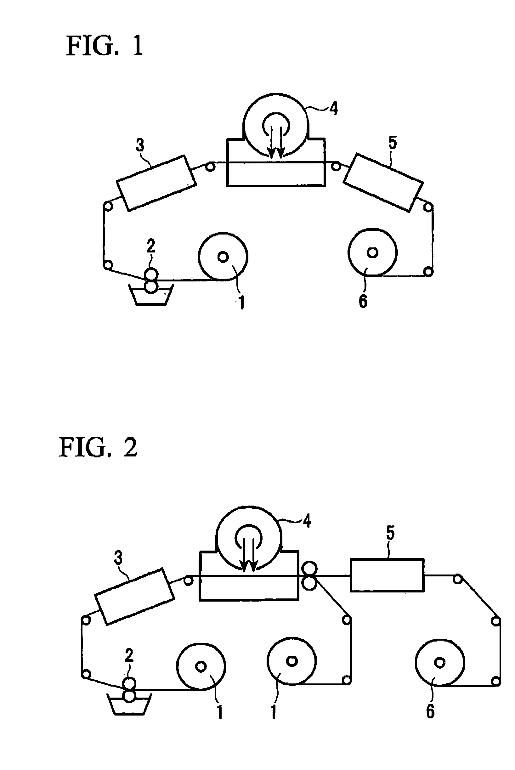
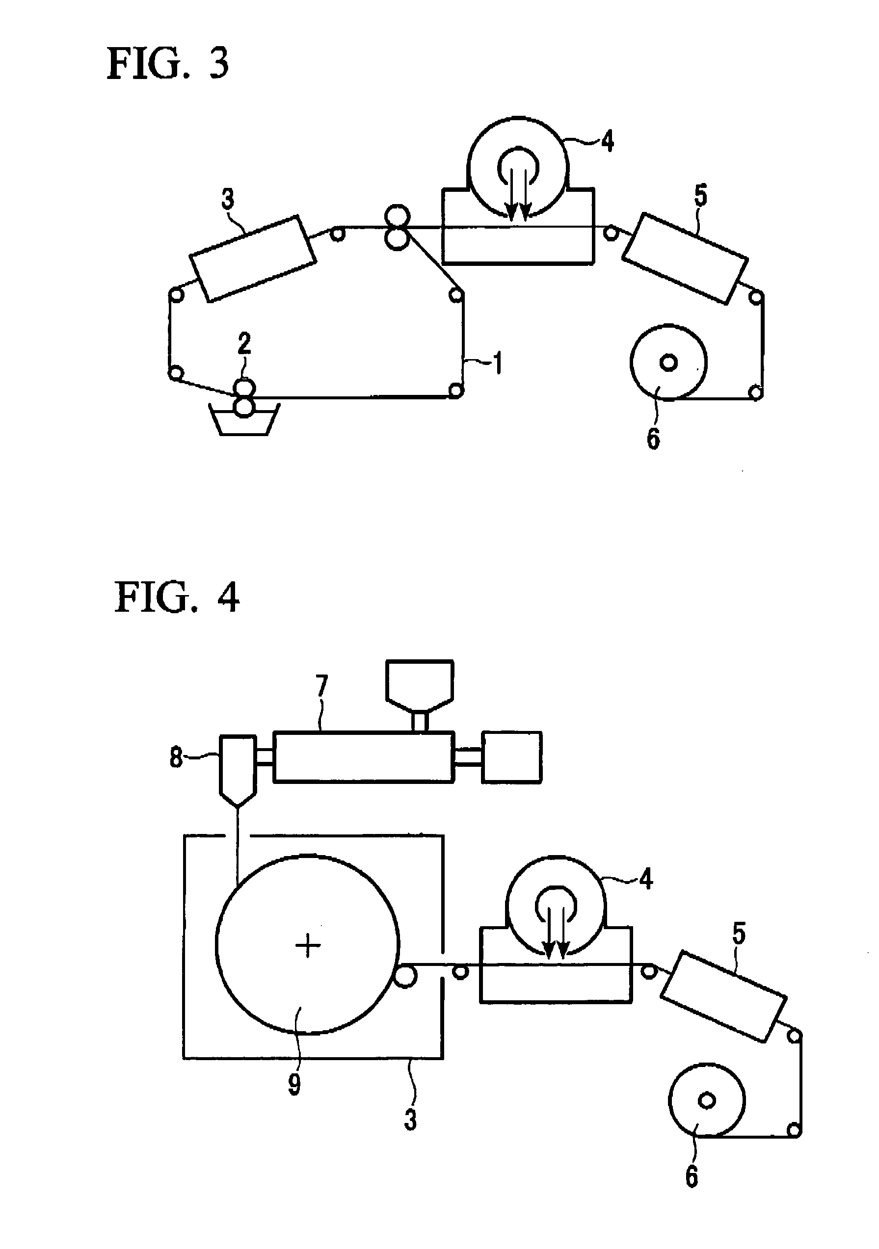
However, it has been extremely difficult to produce thin foams with conventional forming processes.
The main cause of this phenomenon is the cells resulting in the formation of internal defects in the material itself.
This tends to lead to inadequate durability and crack resistance.
However, foam sheets have problems of susceptibility to scratches on the surface of recording materials due to their low surface hardness as well as susceptibility to bending and breaking.
Although it is said that reducing the cell diameter will allow the production of thin foams and foam characteristics that were unable to be achieved in the past, a process has yet to be established that is suitable for these microcellular foams.
In the foaming method proposed by Suh et al. mentioned above, although the cell diameter can be certainly reduced and the cell density can be increased by increasing the amount of impregnated inert gas, these result in the problem of requiring a long period of time for the impregnated inert gas amount to reach saturation.
For example, it has been reported that several days are required to impregnate carbon dioxide into polyethylene terephthalate to saturation, thus causing problems in terms of poor production efficiency.
Since the effects of outgassing increase as the thickness of the forming decreases, defective foaming is often caused when the thickness of the form is 50 μm or less.
Foaming processes that utilize impregnation of an inert gas are faced with a dilemma stemming from the basic principle of these methods in which easily impregnated materials are also susceptible to outgassing, thereby making it extremely difficult to produce microcellular thin foams, and creating the need for the appearance of such foams.
However, in the case of a foam being composed of a polymer material having high moisture absorption and water absorption, when allowed to stand in an environment at a high humidity, the foam gradually adsorbs and becomes impregnated with moisture causing it to soften.
Consequently, there is increased susceptibility to changes in foam dimensions (elongation or contraction) and loss of foam structure (porous structure).
These foams have inadequate foam characteristics which places restrictions on the environmental conditions under which they can be used while also making it difficult to deploy these films in applications.
However, the light reflectors are also required to be thinner accompanying reduced thickness of liquid crystal displays, which tends to decrease the reflection efficiency.
However, since these light reflectors generate leakage current caused by induction current from the light source due to their low electrical resistance, the amount of current used to emit light decreases resulting in the problem of low emission efficiency.
In addition, although there is a need for next-generation, thin light reflecting sheets having a thickness of 100 μm or less, decreasing thickness any further will make it difficult to reduce void diameter.
Moreover, light reflection at the interface between the PET and voids is inadequate, thereby resulting in the problem of decreased reflection efficiency.
However, since the pigment has a higher specific gravity than the resin, the addition of the pigment caused the problem of impairing efforts to reduce weight.
Moreover, the addition of the pigment also worsened dynamic strength and the drawability of the resin (decreased drawing viscosity), which causes the film to break during draw-foaming and results in poor formability and productivity.
In addition, although these films are incorporated in backlighting units, their excessive rigidity makes workability difficult during incorporation in the lamp holder.
However, when the number of hollow elements added in the form of the hollow particles is increased to inhibit decreases in reflection efficiency caused by the use of a thin light reflector, problems are caused in which cracks are formed in the coated layer resulting in poor film formation and the resulting film is extremely brittle.
Consequently, it is difficult to obtain a thin light reflector having high reflection efficiency.

Method used


Image

  • Foam sheet and production process thereof
  • Foam sheet and production process thereof
  • Foam sheet and production process thereof

Examples


example 1

(1) Preparation of a Coating Liquid of a Foamable Composition

[0318]A foam sheet was produced in the following manner. 3 parts of an iodonium salt-based acid generator in the form of bis(4-tert-butylphenyl) iodonium perfluorobutane sulfonate (trade name: BBI-109, manufactured by Midori Kagaku) were mixed with 100 parts of a copolymer of tert-butylacrylate / methyl methacrylate (weight ratio: 60 / 40) used as a decomposing compound, followed by dissolving in ethyl acetate to prepare a solution having a solid content of 25% which was used as a coating liquid. This coating liquid was coated onto one side of a support composed of transparent polyethylene terephthalate (trade name: Lumirror 75-T60, manufactured by Panac) having a thickness of 75 μm using an applicator bar having a gap width of 150 μm. Subsequently, the solvent was removed by evaporation by allowing to stand for 1 minute in a constant temperature dryer at 100° C. A thin film-like, colorless and transparent coated layer was for...

example 2

[0327]A foam sheet in the form of a thin film having microcells was produced in the same manner as Example 1. However, it was heated for 2 minutes at 120° C. in a hot air oven in step (3) of Example 1.

[0328]The results of determining foam thickness, cell diameter and foam expansion ratio in the same manner as Example 1 are shown in Table 3. A thin foaming film having high foam expansion ratio was able to be obtained that was difficult to realize in the prior art.

TABLE 3Foam Structure of Foam Film of Example 2Foam thicknessCell diameterFoam expansion(μm)(μm)ratio6029.1

[0329]The thermal conductivity λ of the film before and after foaming was determined using the equation below from the measured values of thermal diffusivity α, density ρ and specific heat Cp.

λ=α·ρ·Cp

[0330]Thermal diffusivity α was measured using a thermal diffusivity measuring apparatus based on the alternating current heating method (cf. International Journal of Thermophysics, Vol. 18, No. 2, p. 505-513 (1997)). Spec...

example 3

[0332]A foam sheet in the form of a thin film having microcells was produced in the same manner as Example 1. However, a copolymer of tert-butyl acrylate (20% by weight), tert-butyl methacrylate (37% by weight) and methyl methacrylate (43% by mass) was used instead of the poly(tert-butyl acrylate / methyl methacrylate (60 / 40)) used for the decomposing compound in step (1) of Example 1. In addition, ultraviolet light was used instead of the electron beam used for the active energy beam in step (2) of Example 1. This ultraviolet light was irradiated using an ultraviolet irradiation apparatus (manufactured by USHIO INC.) equipped with a Y-ray lamp (of which peak wavelength is 214 nm) at an irradiated dose of 3000 mJ / cm2, followed by heating for 2 minutes at 120° C. in a hot air oven in step (3) of Example 1. At this time, the coated layer changed from a colorless, transparent layer to a white layer in the same manner as Example 1, and a foam sheet was able to be formed having a foam thic...


PUM

PropertyMeasurementUnit
mean cell diameteraaaaaaaaaa
thicknessaaaaaaaaaa
porosityaaaaaaaaaa

Abstract

A foam sheet produced from a foamable composition containing an acid generator that generates acid or a base generator that generates base due to the action of an active energy beam, and containing a compound having decomposing foamable functional group that decomposes and eliminates at least one type of low boiling point volatile substance by reacting with acid or base, makes it possible to obtain a microcellular thin foam that was considered to be difficult to produce thus far, thereby greatly expanding the range of fields in which foams can be used and significantly contributing to industry.

Description

RELATED APPLICATIONS[0001]This application is a divisional of application Ser. No. 10 / 564,791, filed Jan. 13, 2006, which is the U.S. National Phase under 35 U.S.C. § 371 of PCT / JP2004 / 010575, filed Jul. 16, 2004, which claims priority under 35 U.S.C. §119(a)-(d) to Japanese Patent Application No. JP 2003-199515, filed Jul. 18, 2003, and Japanese Patent Application No. JP2003-199521, filed Jul. 18, 2003. The entire contents of these applications is incorporated herein by reference in their entireties.TECHNICAL FIELD[0002]The present invention relates to a foam sheet in which a plurality of independent cells and / or continuous cells is formed and a production process thereof. A foam sheet of the present invention is useful as a foam sheet that is required to demonstrate characteristics such as heat insulation, low dielectric constant, light scattering, light reflection, screening, whiteness, opacity, wavelength-selective reflection and transmittance, light weight, buoyancy, soundproof...

Claims


Application Information

Patent Timeline
Patent Type & Authority Applications(United States)
IPC IPC(8): B32B5/18B01D67/00B01D71/40C08J9/02C08J9/06C08J9/26
CPCB01D67/0023B01D67/009B01D71/40C08J9/06C08J9/26C08J2201/0422B01D2325/44B01D67/0083B01D2323/34B01D2323/46B01D2323/48B01D2325/26C08J2201/046Y10T428/249953C08J9/00C08J9/02
Inventor TAKADA, TOMOYUKIKOJIMA, JUNYA
Owner OJI HLDG CORP
Why Eureka
Try Eureka