Methods and devices for in situ tissue navigation

Inactive Publication Date: 2009-09-03
DREXEL UNIV +1
View PDF12 Cites 33 Cited by
  • Summary
  • Abstract
  • Description
  • Claims
  • Application Information

AI Technical Summary

Benefits of technology

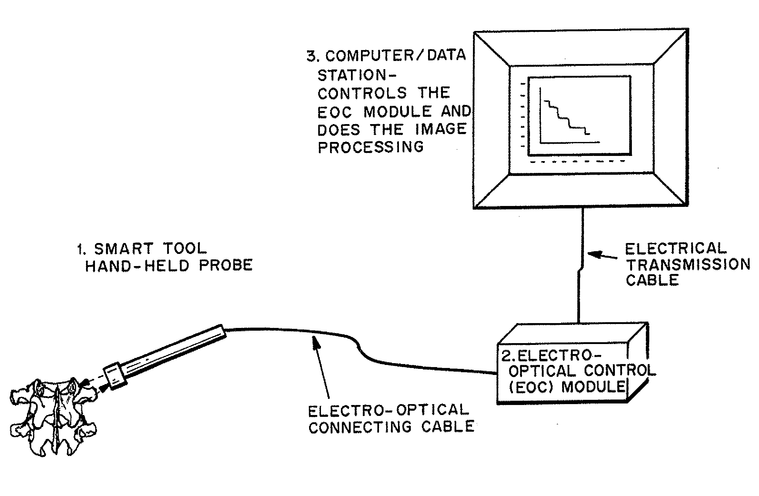
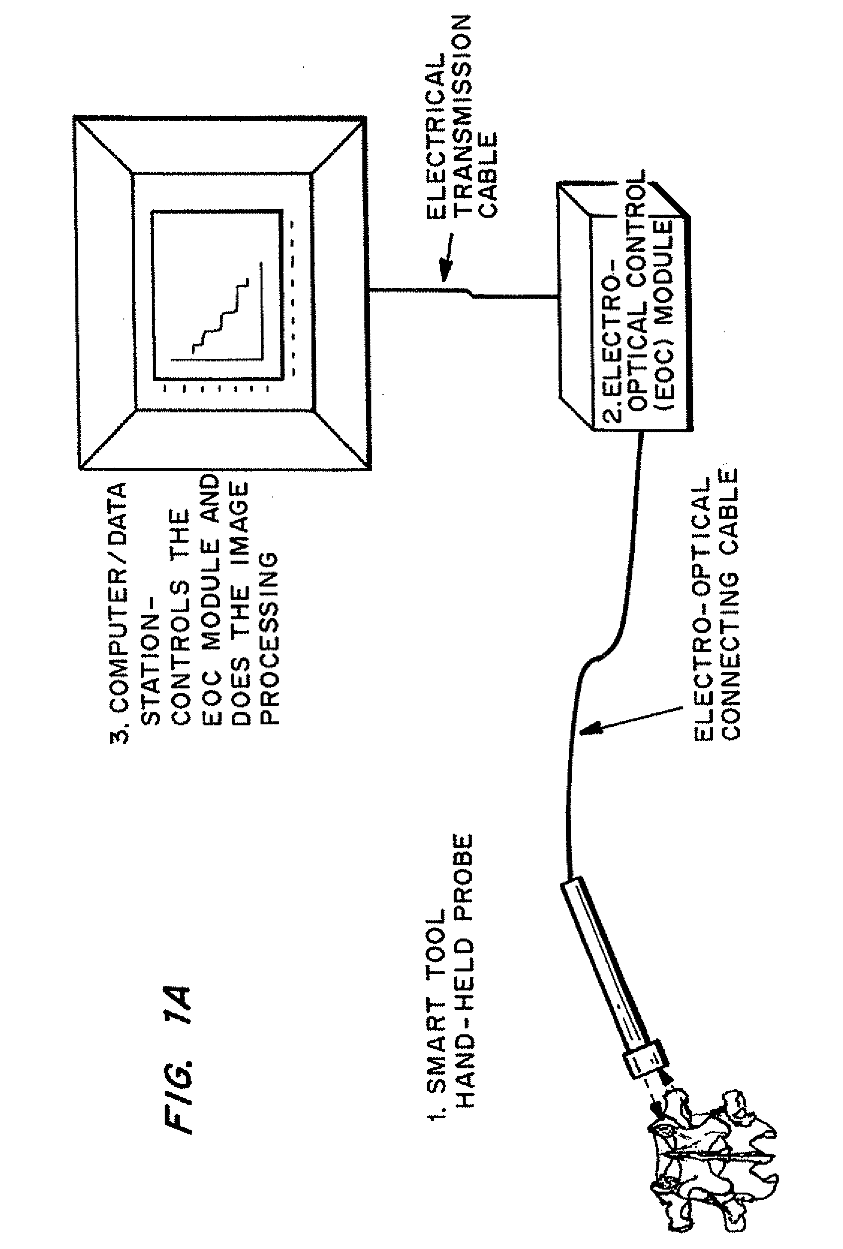
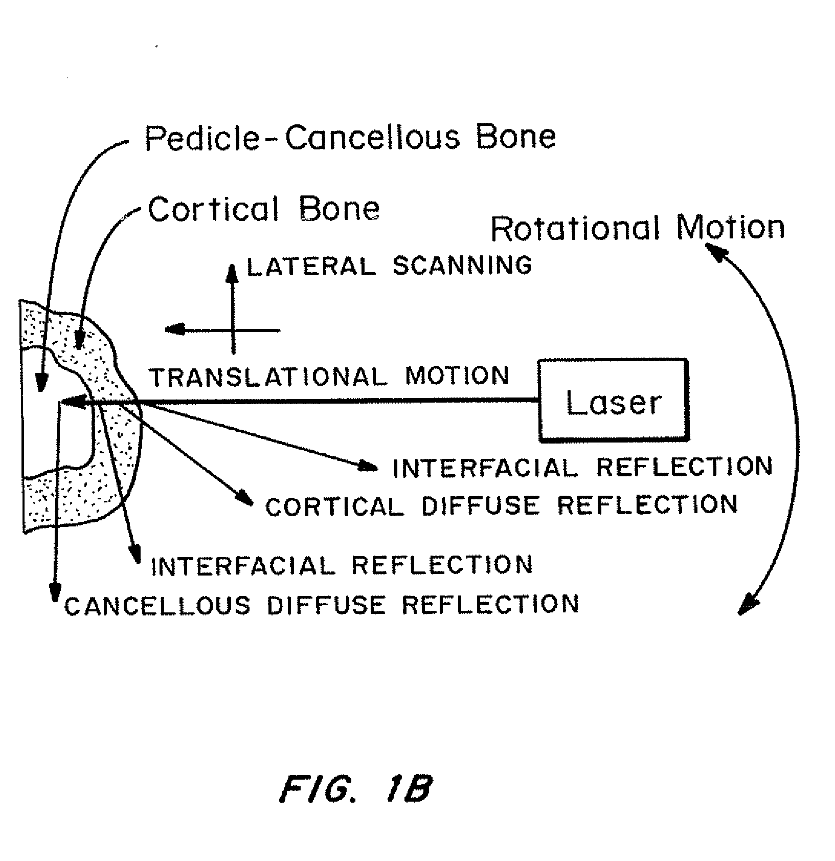
[0035]The system is contained in a hand held tool that can be used by a surgeon to identify the correct entry site and trajectory angle for cannulation (drilling a passage through) a spinal pedicle. The hand tool uses a light source to penetrate and interrogate the bony surface and the bone volume of the spine and collects and relays information to the surgeon regarding the bony topography beneath the instrument tip. This allows the surgeon to select the ideal starting point and trajectory for the placement of a passage through the pedicle.
[0036]The device can be manufactured as a reusable or disposable tool or instrument. Importantly, the tool is designed for surgeons who are familiar with other instruments or tools such as surgical awls or curettes. This should significantly reduce the usual learning curve associated with the use of new technology. In one embodiment, the device has a profiled scanning head enabling matching of the device to the actual shape of the interrogated bone. In another embo

Problems solved by technology

Many problems in modern medicine require diagnostic information of the quality, makeup and substance of the bone of the skeleton.
In another example, the detection of an un-united fusion graft, usually marked by a thin gap within the fusion mass that is filled with fibrous scar tissue, may be difficult to locate precisely.
This situation can lead to pain with movement similar to that experienced with a fracture of a long bone and may require surgical treatment.
All of these structures can be injured during implant placement, leading to catastrophic consequences for the patient and with associated medical-legal implications.
If the trajectory or starting point is not accurate, there is a high risk that the shell of harder cortical bone may be breached, exposing the adjacent spinal cord, nerves or blood vessels to potential damage.
However, the use of radiographic imaging provides only a two-dimensional picture of the complex three-dimensional anatomy of the spine and exposes the surgical team and patient to potentially large amounts of ionizing radiation.
In addition, the equipment is bulky, cumbersome to use, and requires a dedicated technician to operate.
Although this approach seems to be appealing, the use of computer-assisted surgery during spinal surgery has been fraught with difficulties that have limited its use.
For example, the set up and use of the equipment is cumbersome and highly technical.
Additionally, the equipment is bulky and sensitive to being accidentally “bumped” during the procedure, dislodging the reference array attached to the spine and rendering th

Method used


Image

  • Methods and devices for in situ tissue navigation
  • Methods and devices for in situ tissue navigation
  • Methods and devices for in situ tissue navigation

Examples


Embodiment Construction

I. Definitions

[0047]As used herein, “smart” refers to an interactive device that transmits, receives and responds to information.

[0048]As used herein, “information” is a signal that provides information. The signal may be electrical, ultrasonic, laser (or light), radio, or other means of transmission of data.

[0049]As used herein, an “optical fiber” is any conduit through which light can be transmitted, either from a source, or as reflected, scattered, transmitted or diverted by or through a material, such as bone, cartilage or other tissue.

[0050]As used herein, an “optical source” is any optical source such as A laser, optical diode, active fiber, hybrid system emitting monochromatic or multi-wave length light, of different frequencies or wavelengths, including visible, infrared and ultraviolet range, continuously or modulated in amplitude (continuous, pulse modulation), phase and frequency

[0051]As used herein, an “optical receiver” is any optical energy receiving element / device suc...


PUM


Abstract

The “Smart Tool” includes a “Smart Tool Probe” and two processing modules. The Smart Tool Probe is a hand held, wired or wireless, device that a surgeon utilizes for interrogating and identifying a tissue site, such as the entrance to a pedicle. The processing units, an Electro-Optical Control (EOC) Module and a CDS Module, provide control and display capabilities enabling real-time tissue site (such as vertebra bone) interrogation. The Smart Tool Probe utilizes a system of optical fibers that carry the interrogating optical signal sent by the light source(s) and the reflected optical signal back to the optical receivers. The light source(s) and light receivers are located in the EOC Module. The data received from the EOC Module are processed and converted into an image which is displayed on the screen in real-time. The software installed on the machine allows the surgeon to adjust/enhance the image properties to suit the selected requirements. This mode of operation provides interactive image sharpening (to adjust image sharpness), threshold control (to adjust image contrast), segmentation (to delineate the density map in the image), and image calculus (to pin-point the center of a particular region in the image).

Description

CROSS-REFERENCE TO RELATED APPLICATIONS[0001]This application claims priority to U.S. Ser. No. 61 / 033,225 entitled “Methods and Devices for In Situ Tissue Navigation” by Ryszard Lee, Mark R. Goodwin, David Greg Anderson, Daniel Schwartz, and Denis Drummond, filed on Mar. 3, 2008, and is a continuation of PCT / JS09 / 35695, filed Mar. 2, 2009, which also claims priority to U.S. Ser. No. 61 / 033,225.FIELD OF THE INVENTION[0002]The current invention relates to the field of medical instruments and more specifically to devices and methods of use thereof to interrogate bone for the purpose of medical diagnosis or as a surgical tool in the placement of spinal implants during surgery.BACKGROUND OF THE INVENTION[0003]Many problems in modern medicine require diagnostic information of the quality, makeup and substance of the bone of the skeleton. For example, osteoporosis is a bone weakening disease, affecting millions of people around the world. Early diagnosis and treatment of this disease are p...

Claims


Application Information

Patent Timeline
IPC IPC(8): A61B6/00
CPCA61B1/018A61B5/0084A61B5/4504A61B5/4509A61B17/1757A61B17/16A61B17/1615A61B17/1626A61B17/1671A61B5/6848
Inventor LEC, RYSZARDGOODWIN, MARK R.ANDERSON, DAVID GREGSCHWARTZ, DANIELDRUMMOND, DENIS
Owner DREXEL UNIV
Why Eureka
Try Eureka