
Ceramic dielectric or thin and/or thick layers containing at least one ceramic dielectric method for production and use thereof

a ceramic dielectric and dielectric technology, applied in the direction of fixed capacitors, alkaline earth titanates, metallic material coating processes, etc., can solve the problems of electronic circuits no longer managing, many technologies not technically feasible, and phase shifters based on coils having ferrite cores and pin diodes not being established

Inactive Publication Date: 2009-12-03
KERNFORSCHUNGSZENTRUM KARLSRUHE GMBH
View PDF5 Cites 24 Cited by
  • Summary
  • Abstract
  • Description
  • Claims
  • Application Information

AI Technical Summary

Benefits of technology

[0040]Furthermore, it was an object of the present invention to provide a reliable synthetic method for ceramic dielectrics, in particular for doped BST powders, and for thin and / or thick layers thereof.
[0183]The method according to the invention leads to a significant increase in the efficiency of thin and / or thick BST layers.

Problems solved by technology

In many technical areas, ceramics optimized to the specific requirements are key materials without which many technologies would not be technically feasible.
Firstly, these are the structural ceramics which are designed in principle to retain their shape and structure even under strong mechanical, biological, chemical or thermal load.
Electronic circuits now no longer manage without the implementation of dielectric functional ceramics.
In contrast, phase shifters based on coils having ferrite cores and based on PIN diodes have not become established owing to insufficiently fast response times and excessively large dielectric losses and a lack of planar integratability.
Said work on the thick and thin layers is, however, limited substantially to questions relating to measurement.
However, the commercially available controllable components are based on thin BST layers which are produced by means of gas-phase deposition and have the disadvantage that their production is very complicated.
In addition, the difficulty in establishing a defined stoichiometry in the production of thin layers is disadvantageous.
Furthermore, the dielectric properties of thin layers are subject to a strong influence of internal stresses and of lattice parameter differences relative to the substrate.
Thus, high lattice stresses due to differences in the coefficients of thermal expansion as well as the lattice parameters of layer and substrate can lead to reduced permittivity and controllability.
In order to make this controllable or to minimize it, expensive single-crystal substrates are often used as substrates for thin layers or additional buffer layers are applied between substrate and layer, which gives rise to additional processing costs.
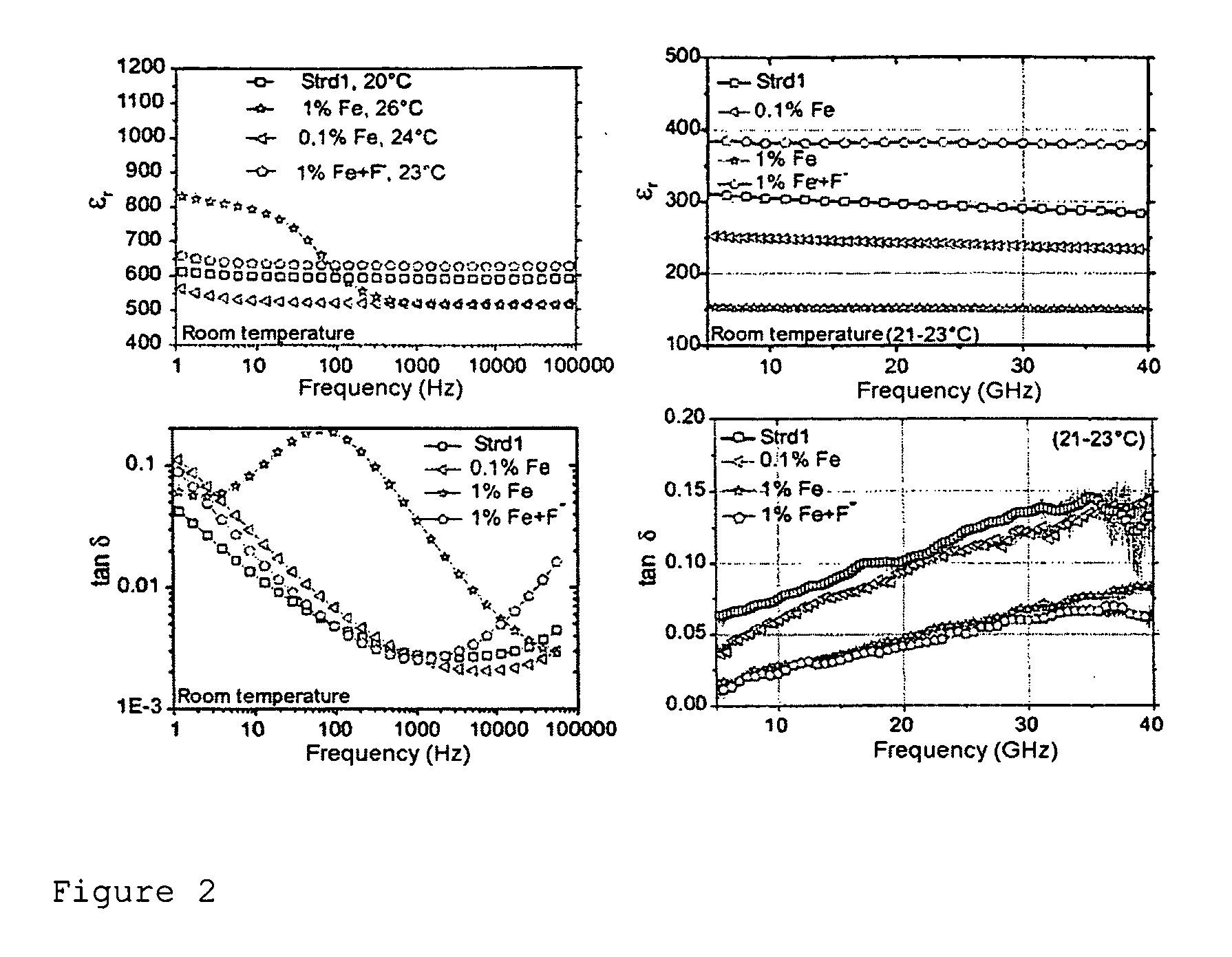
In comparison with thin BST layers, however, thick BST layers have to date shown, at frequencies above 5 GHZ, very greatly increased dielectric losses which additionally increase much more strongly than those of the thin layers at higher frequencies.
The fluoridation is not thermally stable, which means that the material cannot be sintered.
The fluoridation of BT via the gas phase is disclosed in U.S. Pat. No. 3,111,414 but the production of fluoridated BT with metallic codoping is not possible according to this patent.
There too, there is no information about controllable properties.
However, large losses at 1 kHz are also described there and there is no information regarding dielectric properties, only resistance measurements being mentioned.
All HF investigations on thick layers have to date been unsatisfactory.
Thick layers have to date shown extremely large losses in the HF range.
Thin layers have to date been substantially better but firstly they are also substantially more expensive to produce than thick layers and secondly they too show relatively large dielectric losses in the HF range so that they cannot be used commercially at present.
Conclusions about the HF behavior from the low-frequency behavior are not possible or not possible in a satisfactory way since in particular the losses in the HF range are orders of magnitude higher than in the NF range.
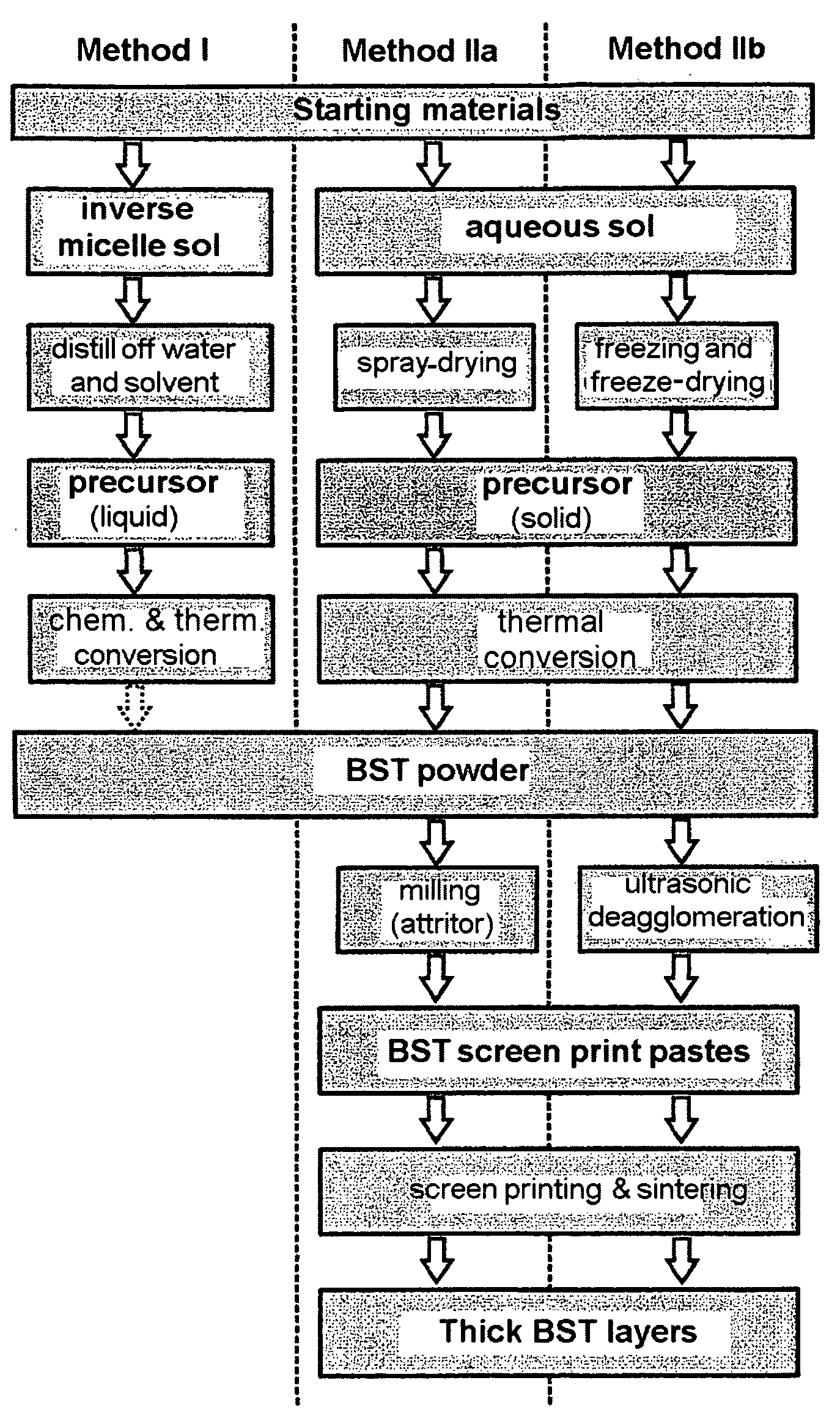
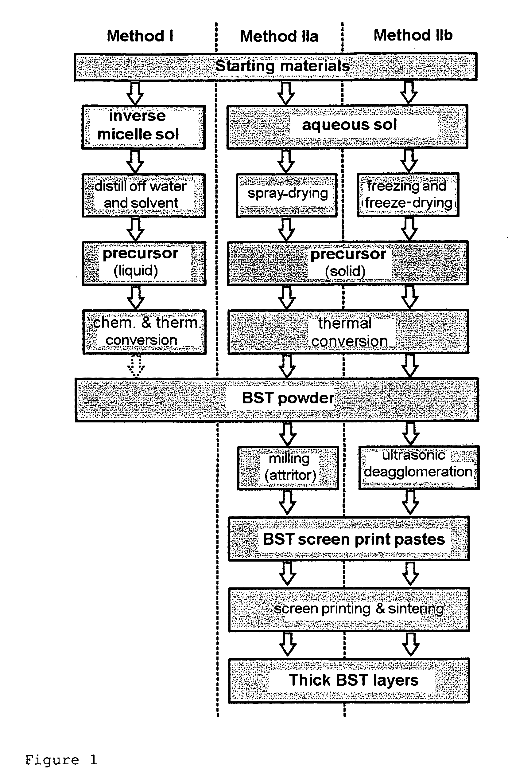
Both methods start from solutions and can thus guarantee a homogeneous distribution of the participating elements at the molecular level with a high degree of conformity to stoichiometry, which cannot be achieved by the mixed oxide and coprecipitation methods.

Method used


Image

  • Ceramic dielectric or thin and/or thick layers containing at least one ceramic dielectric method for production and use thereof
  • Ceramic dielectric or thin and/or thick layers containing at least one ceramic dielectric method for production and use thereof
  • Ceramic dielectric or thin and/or thick layers containing at least one ceramic dielectric method for production and use thereof

Examples


example a

[0194]The synthesis of a sol which corresponded to the amount of 20 g of BST by means of the inverse micelle route was effected as follows:

[0195]7.725 g (56.25 mmol) of barium metal and 3.286 g (37.50 mmol) of strontium metal in approximately pea-sized pieces were added to a solution of 26.64 g of Ti isopropylate (99.75 mmol) in 500 ml (536.70 g, 2.95 mol) of dried diphenyl ether in a nitrogen-flushed, thermostatable glass reactor. The initially white-colored, colloidal solution was thermostated at 70° C., and 6× the stoichiometric amount (67.61 g, 1.125 mol) of dried isopropyl alcohol were added in the course of 7 days. After 7 days, the metals had dissolved. Approximately 3× the molar amount of the alcoholates (3×93.75 mmol) of oleic acid (cis-9-octadecenoic acid, 79.36 g) was added dropwise to the now honey-colored, colloidal solution. The excess isopropanol was then distilled off at 100° C. and atmospheric pressure. Thereafter, 95.74 g (2.82 mol) of a 30% strength H2O2 (“Perhydr...

example b

[0196]The production of a sol via the sol-gel route corresponding to the mass of 20 g of BST powder was carried out as follows: 26.648 g of titanium(IV) isopropanolate (93.75 mmol) were added dropwise to a solution of 14.368 g of barium acetate (56.25 mmol) and 8.052 g of strontium acetate (37.50 mmol) in 240.2 g of glacial acetic acid (4 mol) at room temperature in the glass reactor flushed with N2. An exothermic reaction followed, and a slightly viscous, colorless and clear sol formed. 432.4 g of water (Millipore, filtered) were then added rapidly. A likewise colorless and clear sol having a similar viscosity to water formed. This sol obtained in this manner was suitable for further processing both by spray-drying and by freeze-drying.

example c

[0197]For the production of doped BST, the dopants (Fe, Ta) were added either as hydrolysis-sensitive alcoholates or as water-soluble nitrates. The water-sensitive alcoholate of the Ta dopant was added together with the Ti isopropylate at the beginning of the synthesis via volumetric metering of a stock solution of Ta ethoxide in isopropanol (9.015 mg of Ta ethoxide per ml of solution). The water-soluble nitrates were added as an aqueous solution before the dilution with water. The dopants chosen were Fe3+ as an acceptor, Ta5+ as a donor and Fe3+ together with F− as a mixed acceptor-donor dopant. Iron and tantalum were introduced in two different concentrations as nitrates, and F− was introduced as trifluoroacetic acid (TFA). The addition of water was necessary in order to permit further processing by freeze-drying.


PUM

PropertyMeasurementUnit
Particle sizeaaaaaaaaaa
Frequencyaaaaaaaaaa
Frequencyaaaaaaaaaa

Abstract

The present invention relates to dielectric ceramics, thin and / or thick layers produced therefrom and a method for the production thereof and the use of the dielectrics and of the thin and / or thick layers.

Description

[0001]This application claims the priority of DE 10 2006 017 902.1.[0002]The present invention relates to the field of controllable microwave dielectrics and components based thereon and circuits based on ceramics (ferroelectrics) having small dielectric losses and high controllability (ratio of change in permittivity in the controlled state (with E field) to permittivity in the uncontrolled state (without E field)), i.e. having a high quality.[0003]The present invention also relates to ceramic dielectrics, thin and / or thick layers produced therefrom, for example screen printed thick layers, the use of the ceramic dielectrics and of the thin and / or thick layers, and methods for the production thereof.Definitions[0004]In the context of the present invention, all quantity data are to be understood as meaning weight data, unless stated otherwise.[0005]Unless stated otherwise, the reactions or method steps mentioned are carried out at atmospheric pressure.[0006]In the context of the pre...

Claims


Application Information

Patent Timeline
IPC IPC(8): B32B3/00C04B35/64B05D5/12C23C14/06C04B35/00C04B35/50
CPCC01G23/006Y10T428/24926C04B35/624C04B35/6264C04B35/62655C04B41/009C04B41/5041C04B41/52C04B41/87C04B41/90C04B2111/00844C04B2235/32C04B2235/3206C04B2235/3213C04B2235/3217C04B2235/3224C04B2235/3225C04B2235/3241C04B2235/3251C04B2235/3262C04B2235/3272C04B2235/3275C04B2235/3279C04B2235/3281C04B2235/3284C04B2235/3286C04B2235/3289C04B2235/3291C04B2235/3294C04B2235/441C04B2235/445C04B2235/449H01G4/1227C04B35/4682C04B41/4539C04B41/4537C04B41/5122C04B35/10
Inventor PAUL, FLORIANHAUSSELT, JURGENBINDER, JOACHIMRITZHAUPT-KLEISSL, HANS-JOACHIMGIERE, ANDRESCHEELE, PATRICKJAKOBY, ROLF
Owner KERNFORSCHUNGSZENTRUM KARLSRUHE GMBH
Learn More