Method for manufacturing electrochromic devices
a manufacturing method and electrochromic technology, applied in the field of electrochromic devices, can solve the problems of reducing the lifetime of the device, reducing etc., to achieve high volume and throughput, enhance the manufacturability of the product, and reduce the cost and complexity of the electrochromic device high volume manufacturing
- Summary
- Abstract
- Description
- Claims
- Application Information
AI Technical Summary
Benefits of technology
Problems solved by technology
Method used
Image
Examples
first embodiment
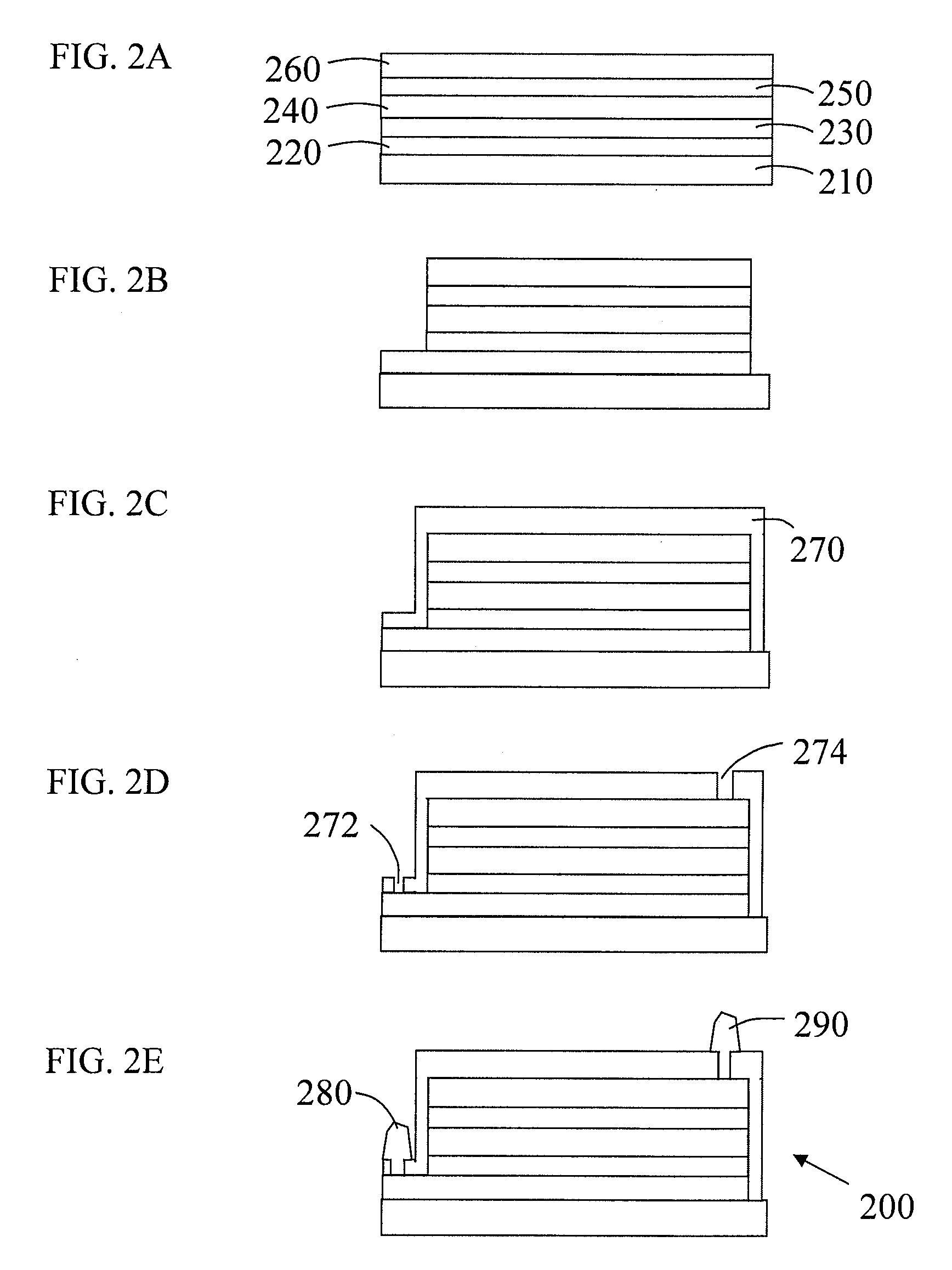
[0022]FIGS. 2A to 2E show a method for manufacturing an electrochromic device 200 according to the invention. FIG. 2A shows a stack of five layers which have been deposited on the substrate 210. The substrate may be glass or plastic. The layers, in order from the substrate, are lower transparent conductive oxide (TCO) layer 220, a cathode 230, a solid electrolyte 240, a counter electrode 250, and an upper TCO layer 260. The layers are deposited one after another using deposition techniques known to those skilled in the art. The lower and upper TCO layers 220 and 260 are typical sputter-deposited indium tin oxide (ITO). The cathode 230 and counter electrode are typically made of transition metal oxides and are typically deposited by physical vapor deposition methods. The solid electrolyte 240 is typically made of ceramic / oxide solid electrolytes such as lithium phosphorus oxynitride and LixSiO2, that can be deposited using various methods including physical and chemical vapor deposit...
second embodiment
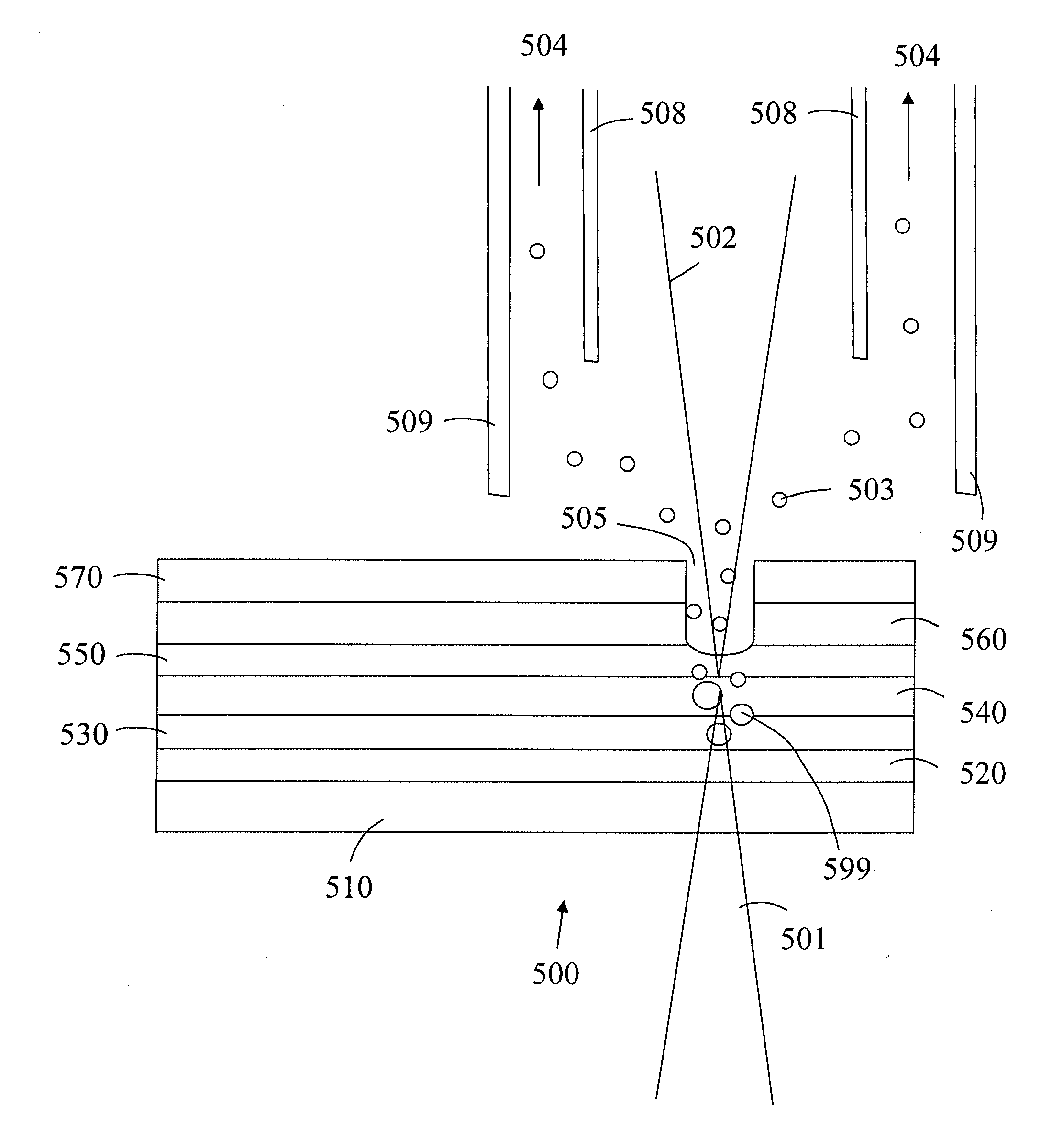
[0023]In the method for manufacturing an electrochromic device according to the invention, the method according to FIGS. 2A through 2C is followed, then the electrical contacts are made through the barrier layer 270, without the need to open up contact areas 272 and 274 in the barrier layer 270. This method of making contact works by diffusing the contact material through the diffusion barrier layer to make an electrically conductive path. This results in the same final device as shown in FIG. 2E, except the first and second electrical contacts 280 and 290 sit on the diffusion barrier layer 270 and make electrical contact to the lower and upper TCO layers 220 and 260, respectively, through the diffusion barrier layer 270 (made locally conductive by contact material diffused into the diffusion barrier layer). This method is applicable when the diffusion barrier layer is either very thin or relatively porous. This may be the case when the demands on the diffusion barrier layer are les...
PUM
 Abstract
Description
Claims
Application Information
 - R&D
- Intellectual Property
- Life Sciences
- Materials
- Tech Scout
- Unparalleled Data Quality
- Higher Quality Content
- 60% Fewer Hallucinations
Browse by: Latest US Patents, China's latest patents, Technical Efficacy Thesaurus, Application Domain, Technology Topic, Popular Technical Reports.
© 2025 PatSnap. All rights reserved.Legal|Privacy policy|Modern Slavery Act Transparency Statement|Sitemap|About US| Contact US: help@patsnap.com


