Anode, cathode, grid and current collector material for reduced weight battery and process for production thereof

a collector material and battery technology, applied in the field of lightweight battery materials, can solve the problems of high cost, increased battery weight, and rigid metal foil when used in prismatic cell design, and achieve the effects of low cost, good adhesion, and high bond strength

Inactive Publication Date: 2009-12-24
MYSTICMD
View PDF17 Cites 45 Cited by
  • Summary
  • Abstract
  • Description
  • Claims
  • Application Information

AI Technical Summary

Benefits of technology

[0014]Therefore, a need has arisen for electrically conductive coatings comprising conductive materials formed from a dispersion, suspension, or mixture of conductive material with low solids concentration that will form a conductive surface, has good adhesion to a chosen substrate, is ductile, has the ability to transfer heat, and is chemically resistant to electrolytes and acids after it is applied to the substrate and cured. The present novel application can be used to inexpensively coat non woven and woven substrates and other materials using a process that can be scaled up to industrial production size and results in materials well-suited for applications where an electrically conductive surface that is ductile, has the ability to transfer heat, is chemically resistant to electrolytes and acids, and has a high bond strength is desired. The substrat

Problems solved by technology

However, the use of copper and aluminum adds cost and results in additional battery weight.
One issue with this construction is that the metal foil when used in a prismatic cell design is very rigid.
However, this is a relatively labor intensive procedure that involves assembly of a number of discrete components, adding weight and cost to the manufacture the battery or cell.
The current collector materials commonly used are lead, copper, aluminum, silver and zinc, all of which add cost to the battery.
However, these approaches fail to provide a battery with the flexibility and durability required in some applications, as well as a simple means for manufacturing.
Processes that use polymer thick film inks have not been capable of providing a conductive layer from which to form an anode or cathode capable of supporting high-energy applications.
Many of the difficulties implementing polymer batteries are related to temperatures found in the battery during discharge and recharging activi

Method used


Image

  • Anode, cathode, grid and current collector material for reduced weight battery and process for production thereof
  • Anode, cathode, grid and current collector material for reduced weight battery and process for production thereof
  • Anode, cathode, grid and current collector material for reduced weight battery and process for production thereof

Examples


example

Preparation and Test Results for Samples

[0050]The first sample (sample 1) was made with a conductive polymer, Acheson Electrodag—PF 427, a polymer ink with ATO that has a low solids content and high resistance level when applied in a thin layer. A mixture of carbon nanotubes was formed by adding 0.056 grams of SWNT selected from a group of carbon nanotubes where the average diameter is less than 20 nanometers, and more preferably less than 10 nm, to 40 ml acetone. The mixture was sonicated using a SANYO MSE SONIPREP 150 tuned to 23 kHz at high power for 30 minutes while ensuring that the acetone level did not drop below the 40 ml mark. In instances in which the acetone dropped below 40 ml, more acetone was added. The solvent temperature was monitored. The mixture was removed from heat and sonication and allowed to cool. The resulting mixture was a dispersion of SWNT.

[0051]In a next step, 0.87 grams of Acheson Electrodag—PF Acheson PF-407C, which is a dispersion of conductive carbon ...

example 2

Battery Manufacture

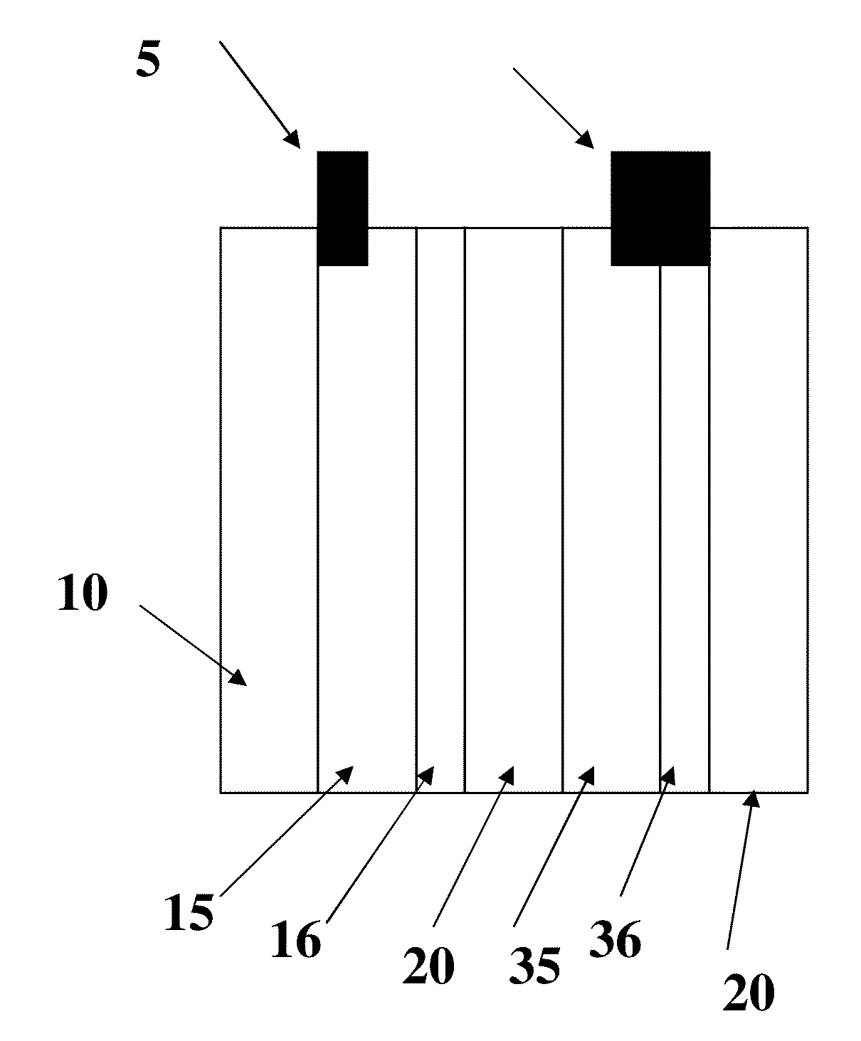
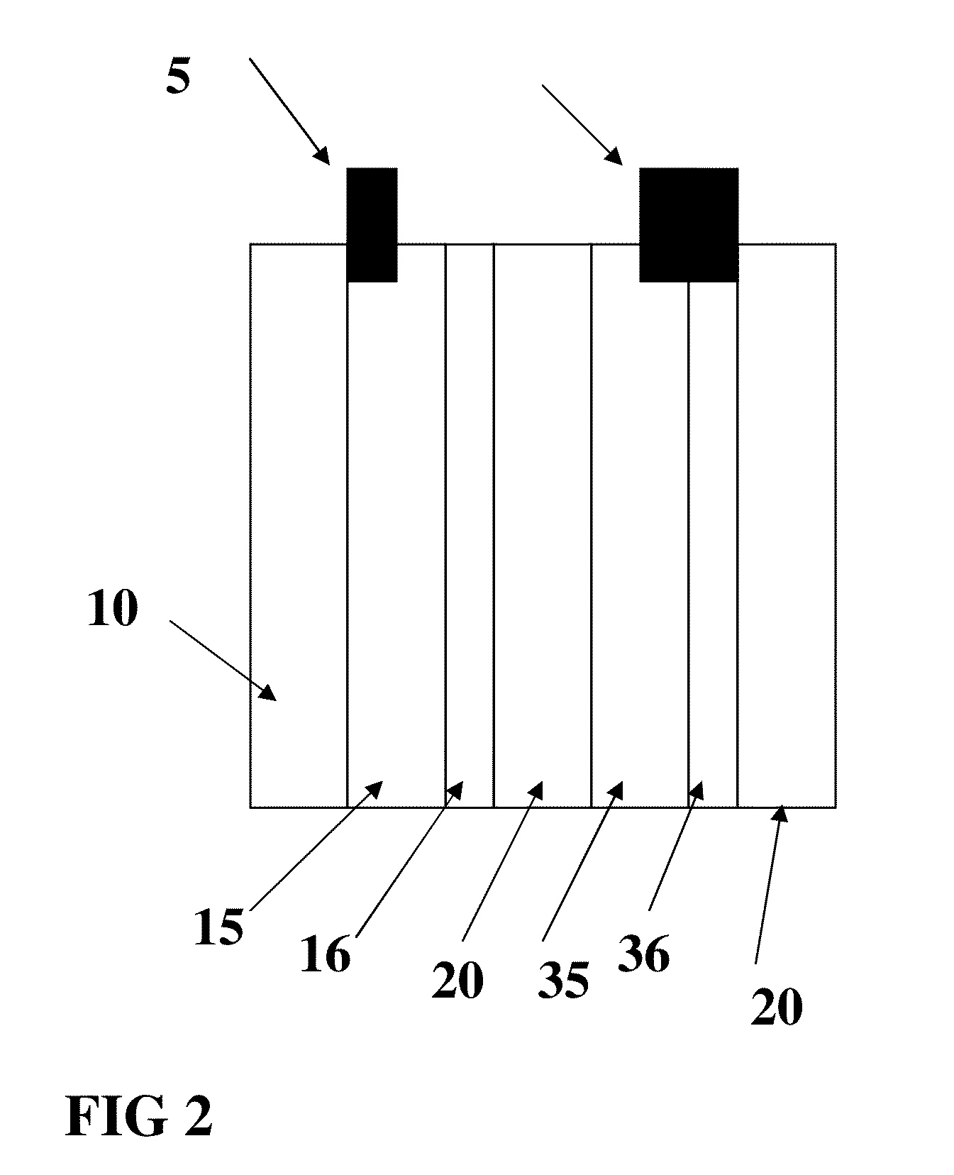
[0058]Referring now to FIG. 2, an anode 15 and an anode current collector 16 was prepared using a dispersion system modified with conductive carbon nanotubes as in sample 1. The material was applied to the substrate (a Hollytex 3234 panel) which was 4 inches by 2 inches to form current collector 16 and dried by warm air at approximately 90 degrees C. for 20 minutes. This panel is shown in FIG. 1. The panel was then coated with a dispersion of 80% by weight of graphite flake and 20% by weight of KYNAR FLEX 2801 polymer binder suspended in N-Methyl-2-Pyrrolidone (NMP) on both sides of the Hollytex panel. The panel was then dried to form anode 15. A copper tab 5 was then welded to the Hollytex panel by using ultrasonic energy as described in co pending application Ser. No. 11 / 897,077 entitled “Bondable conductive ink,” the disclosure of which is incorporated by reference herein. A linen panel 4 inches by 2 inches was then used to form a cathode current collector 36 f...


PUM


Abstract

A process for producing lightweight materials for a battery comprises lightweight polymer substrate coated with dispersions of nano particles, conductive matrixes and active material.

Description

CROSS REFERENCE TO RELATED APPLICATIONS[0001]This application claims the benefits of U.S. Provisional Application No. 61 / 132,688, filed on Jun. 20, 2008, entitled “Anode, cathode, grid and current collector material for reduced weight battery, process for production thereof,” the contents of which are incorporated herein by reference in its entirety.FIELD OF THE INVENTION[0002]The present invention relates to lightweight battery material enabling production of lightweight batteries having large capacity, high voltage, and desirable charge-discharge cycle properties, such material being free from decomposition by the electrolytic solution of the battery; a process for production of anode and cathode materials; a process for production of a current collector material; and a process for production of a grid material for use in lead acid, lithium ion, and silver zinc batteries. The anodes and cathodes are made from electrically conductive coatings formed from dispersions and deposited o...

Claims


Application Information

Patent Timeline
IPC IPC(8): H01M4/02H01M2/02H01M4/04H01M50/121
CPCH01M2/0275H01M2/0277H01M4/668H01M4/663H01M4/667H01M4/0404Y02E60/10H01M50/121
Inventor DOUGLAS, JOEL S.BARBARICH, THOMAS
Owner MYSTICMD
Why Eureka
Try Eureka