
Optical Interferometric Pressure Sensor

a pressure sensor and optical diaphragm technology, applied in the direction of fluid pressure measurement, fluid pressure measurement by electric/magnetic elements, instruments, etc., can solve the problems of increasing the cost of measurement, affecting the sensitive sensor characteristic, and not being able to achieve sup>mbar with silicon, etc., to achieve mechanical stability, reduce cost, and suffer less from temperature expansion distortion

Active Publication Date: 2009-12-31
INFICON HLDG AG
View PDF17 Cites 24 Cited by
  • Summary
  • Abstract
  • Description
  • Claims
  • Application Information

AI Technical Summary

Benefits of technology

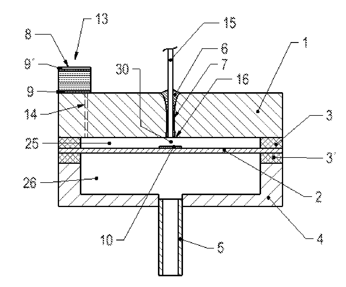
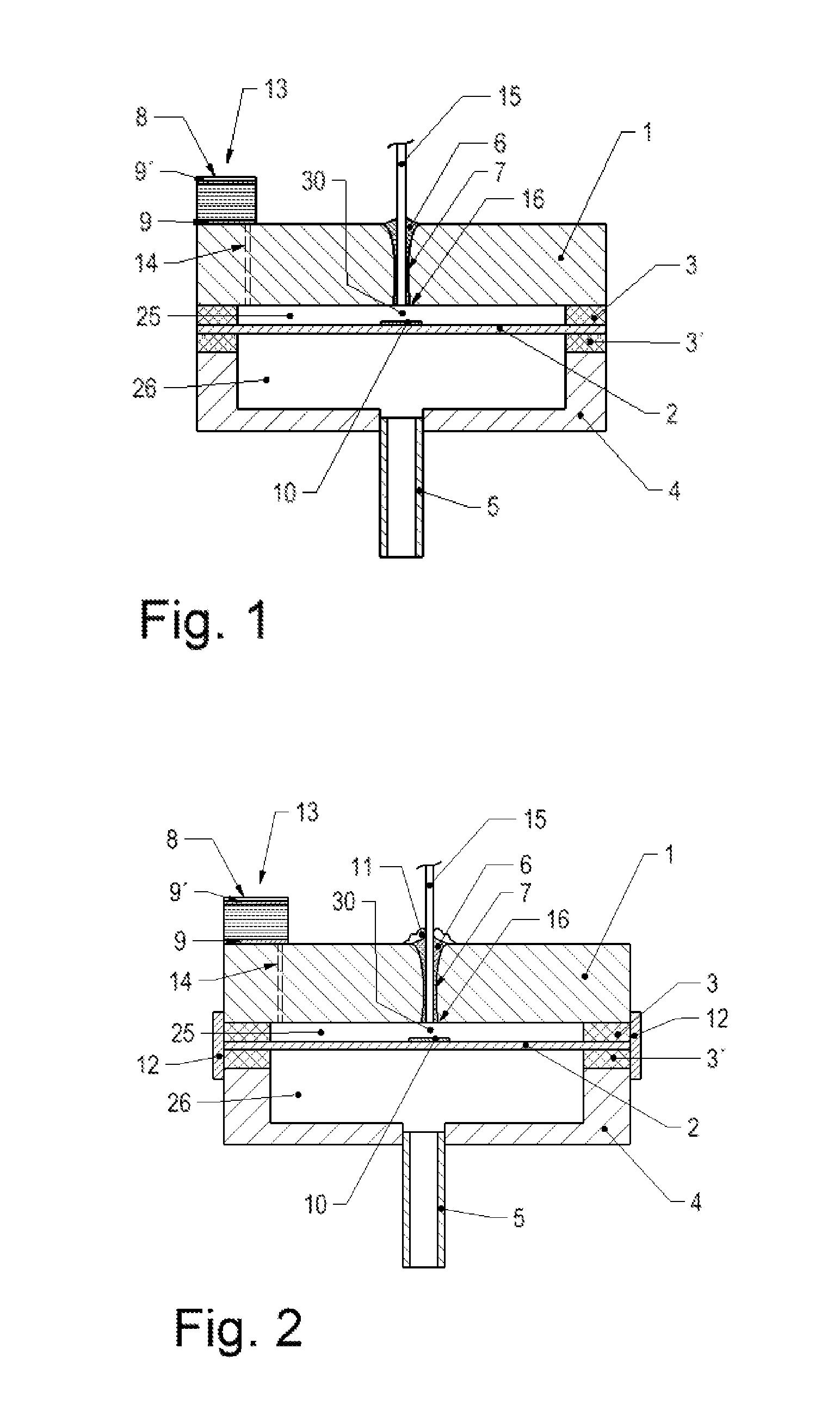
[0029]A high temperature optical fiber, made out of e.g. fused silica or sapphire and coated with a protective coating, such as gold or copper, is attached to a ceramic (preferably Al2O3) ferrule by means of glazing or ceramic adhesive, or directly to a hole in the ceramic body of the sensor cell in such a way, that the fiber end comes through the structure. If a ferrule is used, then it will be attached to a hole in the ceramic body after the fiber attachment in a similar way. After hardening of the ceramic adhesive or the adhesive glass solder, respectively, the fiber end is grinded and / or polished to form the other partly reflecting mirror of the optical cavity to be measured. This polished fiber end can be without an optical coating, or it can be coated, preferably with a single layer of dielectric material, such as Ta2O5, to improve the optical reflectivity.
[0031]Directly-coupled arrangement, compared to an arrangement with external optics, is mechanically very stable and suffers less from temperature expansion distortions than an arrangement with external optics. A reduction of the overall number of parts leads to a cost reduction. The ODG manufacturing cost becomes comparable to a CDG and the performance is better in terms of linearity, repeatability and relative resolution.
[0032]Large numerical aperture, resulting from the fiber characteristics, relaxes the tilting requirements of the optical cavity without requiring any more space for external optics but at the same time restricts the largest measurable gap being ca. 100-200 μm with the practical minimum being at ca. 5 μm due to analysis restrictions of the WLI-technique.
[0035]There is also a positive effect of having an unsmooth substrate surface under the now-formed smooth mirror. Due to viscosity of the glaze when the mirror is formed it is difficult to make a mirror very thin. The refractive index of the glaze is ca. 1.7, which means that e.g. a 6 μm thick mirror creates another optical gap in addition to the actual gap of interest, introducing a clear disturbance in the case of a smooth substrate in the calculated white-light interferogram. If one has a ‘grainy’ substrate, i.e. optically diffuse surface underneath the mirror, then that effect will be minimized.
[0036]However, if the substrate is made as non-diffusive as possible (that is smooth), and the mirror is of proper thickness so that the interference signal created by the glaze mirror layer does not interfere with the interferogram created by the pressure-sensing cavity, one can measure the temperature of the sensor cell by measuring the thickness of the mirror (reacting not to pressure, but only to temperature). At the same time the pressure-indicating gap change would be measured. For example having a mirror of 17 μm in thickness and the resolution of gap measurement of 0.1 nm, one gets as the temperature resolution ca. 0.4° C. Such a sensor could be optimized to be a temperature sensor alone. Making a mirror out of the glass paste gives us a reflection from its surface of only about 7% (approximately same as from the fiber). In fast applications where a lot of broadband light is not available in a short (some milliseconds) time span, the surface of the mirror can be optically coated (preferably a single layer of dielectric material, such as Ta2O5) to enhance the reflection.
[0037]The combination of above-mentioned issues enables one to manufacture an Optical Diaphragm Gauge Sensor (ODG-sensor) out of ceramics by well-known manufacturing processes, decreasing the material and manufacturing costs and relaxing mechanical tolerance requirements significantly. Even though it is not the preferred solution the fibre mounting and the glazing methods also work with sensors made with sapphire components.

Problems solved by technology

However, in vacuum applications pressure sensors of this type are normally usable only for higher pressures in the range of approx.
High resolution at pressures below 10−1 mbar is no longer achievable with silicon.
One of the reasons for this is that the silicon surface reacts with the environment which impairs the sensitive sensor characteristic.
The problem becomes even more serious when the sensor is used in chemically aggressive atmospheres and especially with higher temperature up to some hundreds degree Celsius.
Such measures are costly and in the case of mechanically deformable parts such as membranes have only limited success, in particular in highly aggressive media such as fluorine, bromic acid and their compounds which are typically used in vacuum etching processes.
A disadvantage with using sapphire alone in the sensor cell is its price—machined single-crystal sapphire is very expensive.
Secondly, having a combination of sapphire and ceramic Al2O3 introduces a small mismatch in the Coefficient of Thermal Expansion (CTE), which might pose problems in the temperature drift behavior, for example.
To reduce this effect requires proper crystal orientation, an expensive and time consuming process.
In addition a large number of components are needed which makes the production of such a sensor cell costly.

Method used


Image

  • Optical Interferometric Pressure Sensor
  • Optical Interferometric Pressure Sensor

Examples


Embodiment Construction

[0042]The preferred inventive arrangement of an ODG (Optical Diaphragm Measuring Cell) measuring cell made of Al2O3 with a structure essentially symmetrical about the membrane 2 is illustrated by the cross-section in FIG. 1. The first housing 1 body consists of a ceramic plate made of Al2O3 which along its edges is tightly bonded at a distance of 5 μm to 80 μm relative to the ceramic membrane 2 and which encloses a reference pressure chamber 25 which is preferably a vacuum chamber. The distance between the two surfaces is usually established directly during the assembly by means of the sealing material 3, 3′ located between the membrane edge and the housing. In this way a completely plane housing plate 1 can be used. In the same way a measurement pressure chamber 26 is formed in a second housing body 4 on the opposite membrane side; this pressure chamber is accessible for the media to be measured via a connecting port 5 through an opening in the housing 4. The cell arrangement is es...


PUM

PropertyMeasurementUnit
temperaturesaaaaaaaaaa
thicknessaaaaaaaaaa

Abstract

A pressure measuring cell has a first housing body and a membrane arranged proximate the housing body, both of ceramic. The membrane has a peripheral edge joined to the first housing body to create a reference pressure chamber. A second housing body made of ceramic material is opposite the membrane and is joined to the peripheral edge of the membrane, the second housing body together with the membrane forming a measurement pressure chamber. The second housing body has a port for connecting the pressure measuring cell to a medium to be measured. The first housing body, the second housing body and the membrane are tightly connected along the peripheral edge of the membrane in a central area of the first housing body a hole is formed, reaching through the first housing body and at least in the central region of the membrane and opposite the hole a surface of the membrane is formed as a first optically reflective area. An optical fiber is arranged and tightly fixed within the hole for feeding light onto the surface of the membrane. The end of the fiber reaches at least the surface of the first housing body and is formed as a second reflective optical area linking the surface so that between the fiber end and the reflection area an optical cavity is present which forms a measuring section for determining the level of deflection of the membrane and which is part of a Fabry-Perot Interferometer.

Description

FIELD OF THE INVENTION[0001]The invention relates to an optical diaphragm gauge for measuring high vacuum pressure in a wide pressure range.DESCRIPTION OF THE RELATED ART[0002]It is known that pressures or pressure differences can be measured by applying pressure to a thin membrane and measuring its deflection. A known and suitable method for measuring the deflection is to design the membrane arrangement as a variable electrical capacitance where the capacitance change which correlates with the pressure change is evaluated by measurement electronics in a known manner. The capacitance is created by arranging a thin, flexible membrane very close to another surface and by depositing an electrically conductive film on both mutually opposed surfaces or by fabricating them from electrically conductive material. When pressure is applied to the membrane the deflection changes the distance between the two electrodes which leads to an analyzable capacitance change of the arrangement. Sensors ...

Claims


Application Information

Patent Timeline
Patent Type & Authority Applications(United States)
IPC IPC(8): G01L9/12G01B9/02
CPCC04B37/005C04B2237/064C04B2237/10C04B2237/343Y10T29/49776C04B2237/74G01L9/0079Y10T29/49002C04B2237/704
Inventor ANTILA, JARKKOBERTSCH, DIETMARMULLIS, FELIXWUEST, MARTIN
Owner INFICON HLDG AG
Learn More