[0016]An
advantage of the present invention is in providing a method for fabricating a microfluidic device with one or more cylindrical microchannels that can be used to model microvasculature of animals and humans.
[0017]An
advantage of the present invention is in combining photonic and microfluidic devices to create geometries with additional functionality, compactness, and enhanced integration. A microfluidic device in accordance with the present invention that incorporates photonically significant geometries such as
fiber waveguides, photonic crystals, and the like, allows fluids to infiltrate the devices and to modify the local optical environment of the device. Further, the microfluidic device may be modified in this fashion to provide tunability that did not exist in the original photonic structure. Additional tunability features may be incorporated by varying the chemical and optical properties of the fluid itself. Conversely, the nature and composition of the fluid may be determined by observing the response of a photonic structure with known behavior. These optofluidic structures may perform
optical sensing.
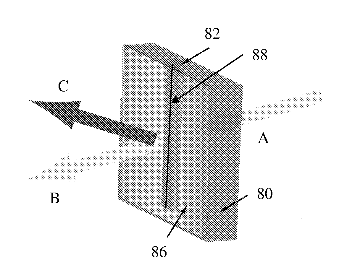
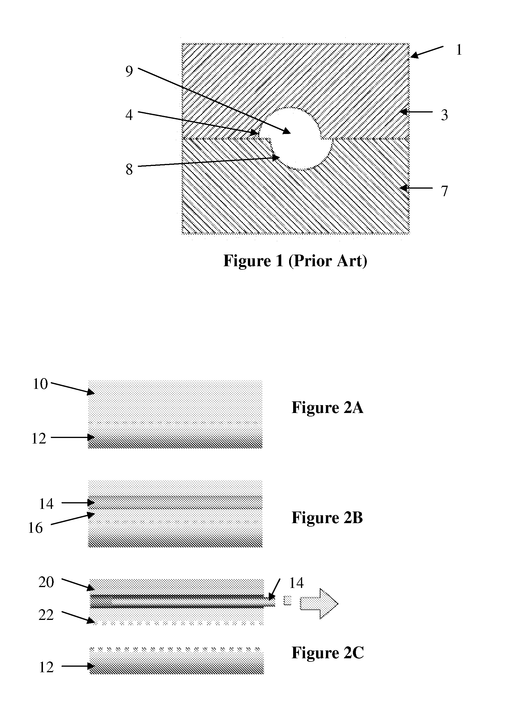
[0018]In the above regard, a method of manufacturing a microfluidic device having at least one cylindrical microchannel is provided in accordance with one aspect of the present invention. In one embodiment, the method includes providing a substrate,
casting an uncured polymer matrix solution onto the substrate, embedding an elongated rod in the uncured polymer matrix solution, curing the polymer matrix solution to form a solidified body of the microfluidic device, and extracting the elongated rod to form the cylindrical microchannel in the solidified body. In this regard, the method may also include suspending the elongated rod over the substrate.
[0019]In one embodiment, the elongated rod is a silica rod having a diameter between approximately 40 μm and 250 μm, for example between approximately 57 μm and 125 μm. In one embodiment, the
biopolymer matrix solution is a silk
fibroin matrix solution having approximately 1.0 wt % to 30 wt % silk, inclusive. For example, the silk
fibroin matrix solution may have approximately 8.0 wt % silk. In another embodiment, the polymer matrix solution is
polydimethylsiloxane (PDMS). In another embodiment, the polymer matrix solution is a
biopolymer such as
chitosan, collagen,
gelatin,
agarose,
chitin,
polyhydroxyalkanoates, pullan,
starch (
amylose amylopectin),
cellulose,
hyaluronic acid, and related biopolymers, or variations or combinations thereof. In still another embodiment, the method of the present invention may further include applying heat to the uncured polymer matrix solution to cure the solution. In addition, the method may further include
coating the silica rod with a surfactant solution.
[0020]In yet another embodiment, the method of the present invention may include forming an optical element on a surface of the microfluidic device or upon a substrate. In this regard, the substrate may be a template for an optical element such as a lens, a
microlens array, an optical
grating, a pattern generator, a beam reshaper, a mirror blank, or a
glass slide. In another embodiment, the method may further include adding a
doping agent to the uncured polymer matrix solution, where the
doping agent may be an organic material such as red blood cells,
horseradish peroxidase, phenolsulfonphthalein, or a combination thereof. The organic material can also be a
nucleic acid, a dye, a
cell, an
antibody, enzymes, for example,
peroxidase,
lipase,
amylose,
organophosphate dehydrogenase, ligases, restriction endonucleases, ribonucleases,
DNA polymerases,
glucose oxidase,
laccase, cells, viruses, proteins, peptides, small molecules, drugs, dyes, amino acids, vitamins, antixoxidants,
DNA,
RNA, RNAi, lipids, nucleotides, aptamers, carbohydrates, chromophores, light emitting organic compounds such as
luciferin, carotenes and light emitting inorganic compounds, chemical dyes,
antibiotics, antifungals, antivirals, light harvesting compounds such as
chlorophyll, bacteriorhodopsin, protorhodopsin, and porphyrins and related electronically active compounds, or a combination thereof.
[0021]In accordance with another aspect of the present invention, a microfluidic device is provided, the device comprising a polymer body and at least one cylindrical microchannel in the polymer body where the cylindrical microchannel has a diameter between approximately 40 μm and 250 μm, inclusive. For example, the cylindrical microchannel may have a diameter between approximately 57 μm and 125 μm, inclusive. The polymer body may be made of
polydimethylsiloxane (PDMS) in one embodiment, but in other embodiments the polymer body may be made of a
biopolymer such as silk,
chitosan, collagen,
gelatin,
agarose,
chitin,
polyhydroxyalkanoates, pullan,
starch (
amylose amylopectin),
cellulose,
hyaluronic acid, and related biopolymers, or a combination or variation thereof. In addition, the polymer body may be implemented to include a
doping agent and an optical element on a surface of the polymer body. The doping agents may include organic materials such as red blood cells,
horseradish peroxidase, and phenolsulfonphthalein, for example. The optical elements may include a lens, a
microlens array, an optical grating, a pattern generator, a beam reshaper, a mirror blank, and a
glass slide. The organic material can also be a
nucleic acid, a dye, a
cell, an
antibody, enzymes, for example,
peroxidase,
lipase, amylose,
organophosphate dehydrogenase, ligases, restriction endonucleases, ribonucleases,
DNA polymerases,
glucose oxidase,
laccase, cells, viruses, proteins, peptides, small molecules, drugs, dyes, amino acids, vitamins, antixoxidants, DNA,
RNA, RNAi, lipids, nucleotides, aptamers, carbohydrates, chromophores, light emitting organic compounds such as
luciferin, carotenes and light emitting inorganic compounds, chemical dyes,
antibiotics, antifungals, antivirals, light harvesting compounds such as
chlorophyll, bacteriorhodopsin, protorhodopsin, and porphyrins and related electronically active compounds, or a combination thereof.

