Monolithic Multinozzle Emitters for Nanoelectrospray Mass Spectrometry

a multi-nozzle, nanoelectrospray technology, applied in the direction of boring tools, isotope separation, particle separator tubes, etc., can solve the problems of large opportunities and challenges in mass spectrometry, sensitivity and dynamic range have not been sufficient for all analyses, and it is difficult to detect many of the less abundant proteins

Active Publication Date: 2010-03-25
RGT UNIV OF CALIFORNIA
View PDF1 Cites 22 Cited by
  • Summary
  • Abstract
  • Description
  • Claims
  • Application Information

AI Technical Summary

Problems solved by technology
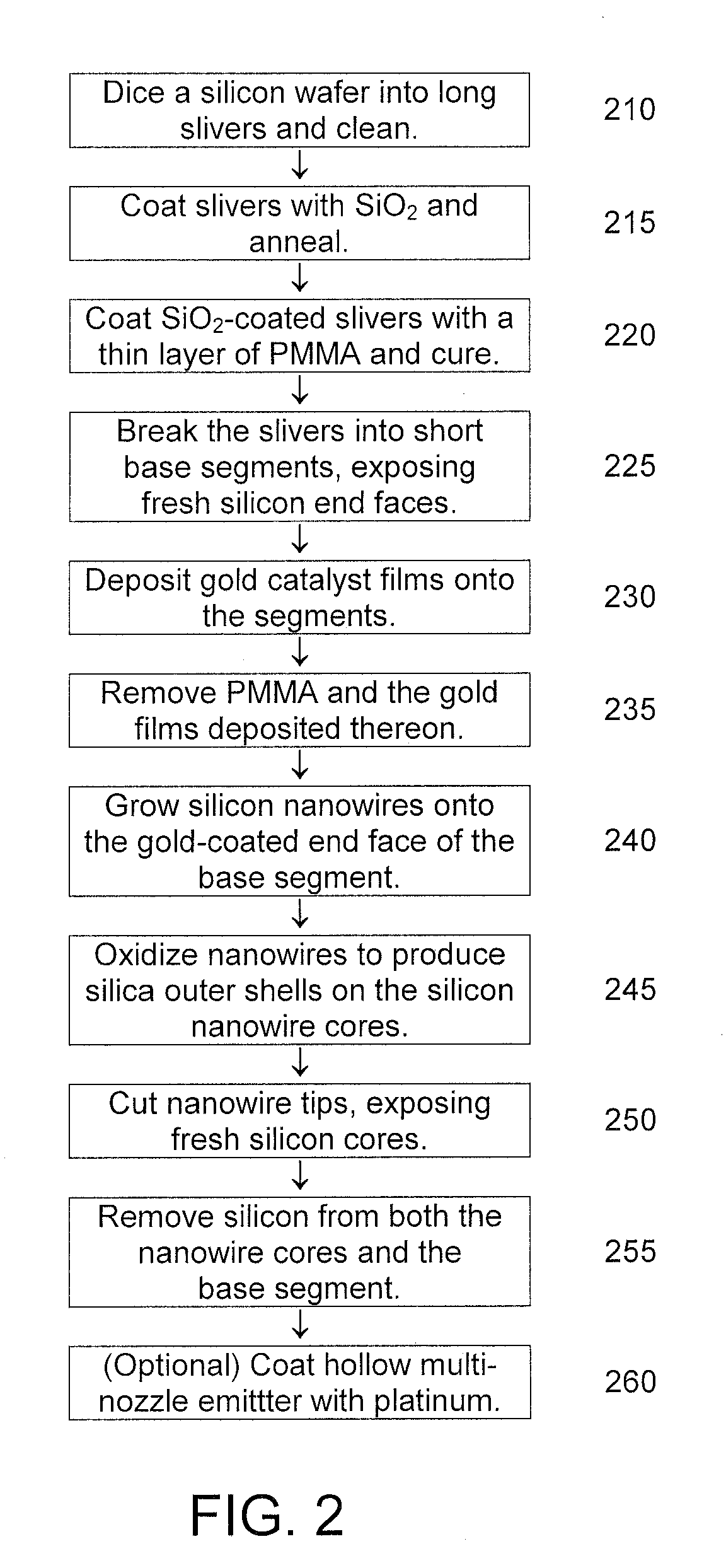
However, there still remain great opportunities and challenges in mass spectrometry.
Yet, the sensitivity and dynamic range have not been sufficient for all analyses.
However, due to the huge dynamic range (106-109) of proteins in the cell, it still remains a challenge to detect many of the less abundant proteins, even those that are present in large amounts.
Thus there is a limited dynamic range, which can be a serious drawback.
In a complex mixture this problem can be especially severe.
But there are difficulties associated with fabrication of such small capillaries, and there can be problems with increased back pressures from such extremely small channels.
In addition, very small capillaries can lead to low throughput because of the need for careful and tedious alignment in the mass spectrometer.
However, inherent properties of these hydrophobic polymers, such as strong binding affinity to proteins and incompatibility with organic solvents, have limited their usefulness for electrospray applications.
In-plane silicon nitride emitter fabrication has failed due to intrinsic clogging problems arising from the etching of phosphosilicate glass between silicon nitride layers.
Out-of-plane fabrication of silicon / silica has been limited critically because of the additional assembly steps needed to attach emitters to the end of a microfluidic channel.
None of these emitters has achieved desired flow rates of pL / min or less.
In addition, no monolithic multinozzle emitter for nanoelectrospray mass spectrometry has ever been fabricated.

Method used


Image

  • Monolithic Multinozzle Emitters for Nanoelectrospray Mass Spectrometry
  • Monolithic Multinozzle Emitters for Nanoelectrospray Mass Spectrometry
  • Monolithic Multinozzle Emitters for Nanoelectrospray Mass Spectrometry

Examples


Embodiment Construction

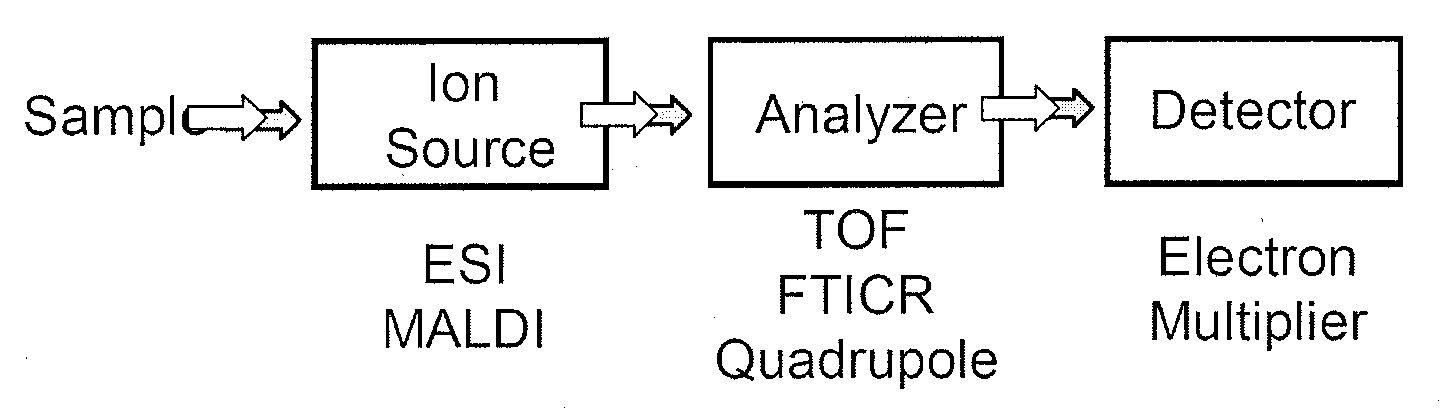
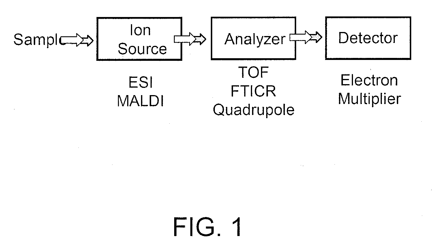
[0012]The embodiments of the invention are illustrated in the context of nanoelectrospray emitters for mass spectrometry. The skilled artisan will readily appreciate, however, that the materials and methods disclosed herein will have application in a number of other contexts where very small droplet size and very slow fluid flow rates are desirable.

[0013]The terms “nozzle,”“capillary,” and “tubule” are used interchangeably in this disclosure to mean a very thin tube out of which an analyte solution can flow and form small droplets. The term “emitter” is used to mean the assembly that includes both the nozzle(s) and a base chamber or tube that supplies an analyte solution to the nozzle(s). In the case of a single nozzle, the terms “emitter” and “nozzle” can refer to the same structure as there is a one-to-one correspondence between the nozzle and its base chamber; the base chamber can be thought of as a simple extension of the nozzle. The term “trench” is used to mean a groove or dit...


PUM

PropertyMeasurementUnit
droplet diametersaaaaaaaaaa
flow ratesaaaaaaaaaa

Abstract

Novel and significantly simplified procedures for fabrication of fully integrated nanoelectrospray emitters have been described. For nanofabricated monolithic multinozzle emitters (NM2 emitters), a bottom up approach using silicon nanowires on a silicon sliver is used. For microfabricated monolithic multinozzle emitters (M3 emitters), a top down approach using MEMS techniques on silicon wafers is used. The emitters have performance comparable to that of commercially-available silica capillary emitters for nanoelectrospray mass spectrometry.

Description

CROSS-REFERENCE TO RELATED APPLICATIONS[0001]This application is a continuation application of PCT Application No. PCT / US2007 / 066678 filed on Apr. 15, 2007 which claimed priority to U.S. Provisional Patent Application 60 / 746,012, filed Apr. 28, 2006, both of which are hereby incorporated by reference in their entirety.STATEMENT OF GOVERNMENTAL SUPPORT[0002]The invention described and claimed herein was made in part utilizing funds supplied by the U.S. Department of Energy under Contract No. DE-AC02-05CH11231 and in part utilizing funds supplied by National Institutes of Health Grant R21GM077870. The U.S. Government has certain rights in this invention.TECHNICAL FIELD[0003]This invention relates generally to electrospray ionization emitters for mass spectrometry, and, more specifically, to methods for forming such emitters for nanoelectrospray mass spectrometry for proteomic and metabolomic applications.BACKGROUND ART[0004]Mass spectrometry measures the mass-to-charge ratio (m / z) of ...

Claims


Application Information

Patent Timeline
Patent Type & Authority Applications(United States)
IPC IPC(8): G01N33/53H01J49/10B29C71/00B44C1/22
CPCB01L3/5027H01J49/165H01J49/0018B82Y15/00
Inventor WANG, DAOJINGYANG, PEIDONGKIM, WOONGFAN, RONG
Owner RGT UNIV OF CALIFORNIA
Why Eureka
Try Eureka