

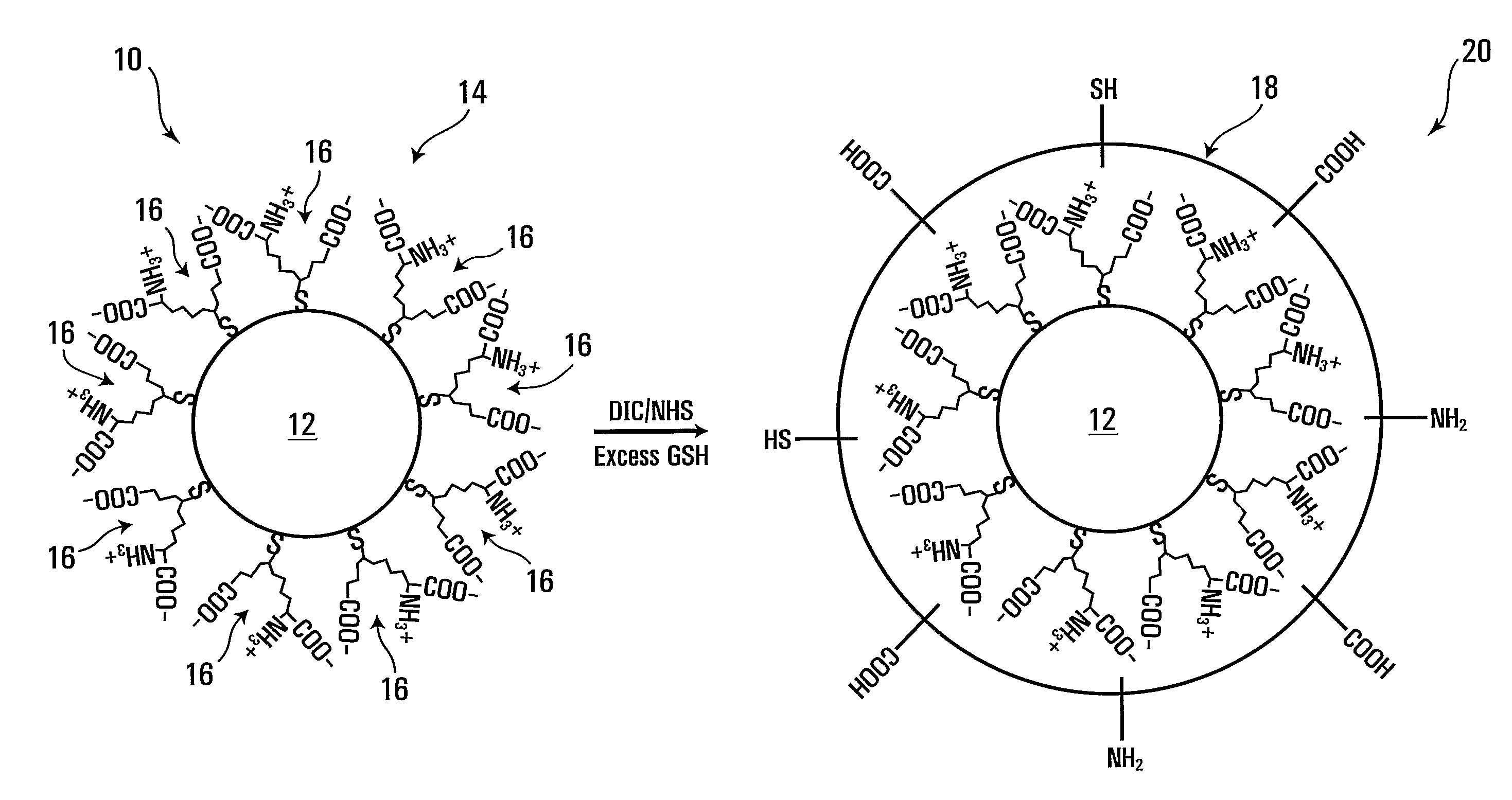
Forming crosslinked-glutathione on nanostructure
a nanostructure and crosslinked glutathione technology, applied in the field of nanostructures, can solve the problems of difficult formation of a layer of such materials, limited application of large qds, and inability to use small targets
- Summary
- Abstract
- Description
- Claims
- Application Information
AI Technical Summary
Benefits of technology
Problems solved by technology
Method used
Image

Examples
examples
[0081]For these examples, diisopropyl carbodiimide, sodium hydroxide, zinc chloride, cadmium chloride, aluminum telluride, zinc acetate, and cadmium acetate were obtained from Lancaster™; trioctylamine (TOA), trioctylphosphine (TOP), oleic acid, cadmium oxide (CdO), cadmium acetate dehydrate, selenium (Se) powder (200 mesh), L-glutathione, sulfur powder, and NHS were obtained from Sigma-Aldrich™; octadecylphosphonic acid and cetyltrimethylammonium bromide (CTAB) were obtained from Alfa™, unless otherwise specified. These chemicals were all of a high purity grade, which is more precisely indicated below for some of these chemicals.
example i
Synthesis of uGSH-CdTe QDs
[0082]All reactions in this example were performed in oxygen-free water under argon. The synthesis of CdTe QDs was based on the reaction of cadmium chloride with hydrogen telluride. The tellurium precursor, H2Te, was prepared by adding 0.5 M of sulfuric acid drop-wise to a lump of aluminum telluride (Al2Te3). Freshly generated H2Te gas was bubbled into a solution containing CdCl2 and GSH at pH 11.5 with vigorous stirring. The amounts of Cd, Te and GSH were 5, 1 and 6 mmol, respectively, in a total volume of 500 ml. The resulting dark yellow mixture was heated to 95° C., and the growth of GSH-CdTe QDs took place immediately.
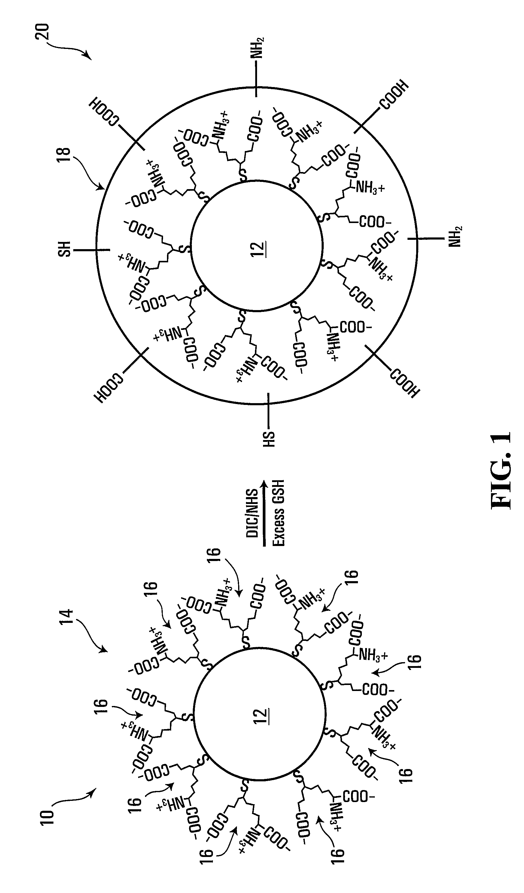
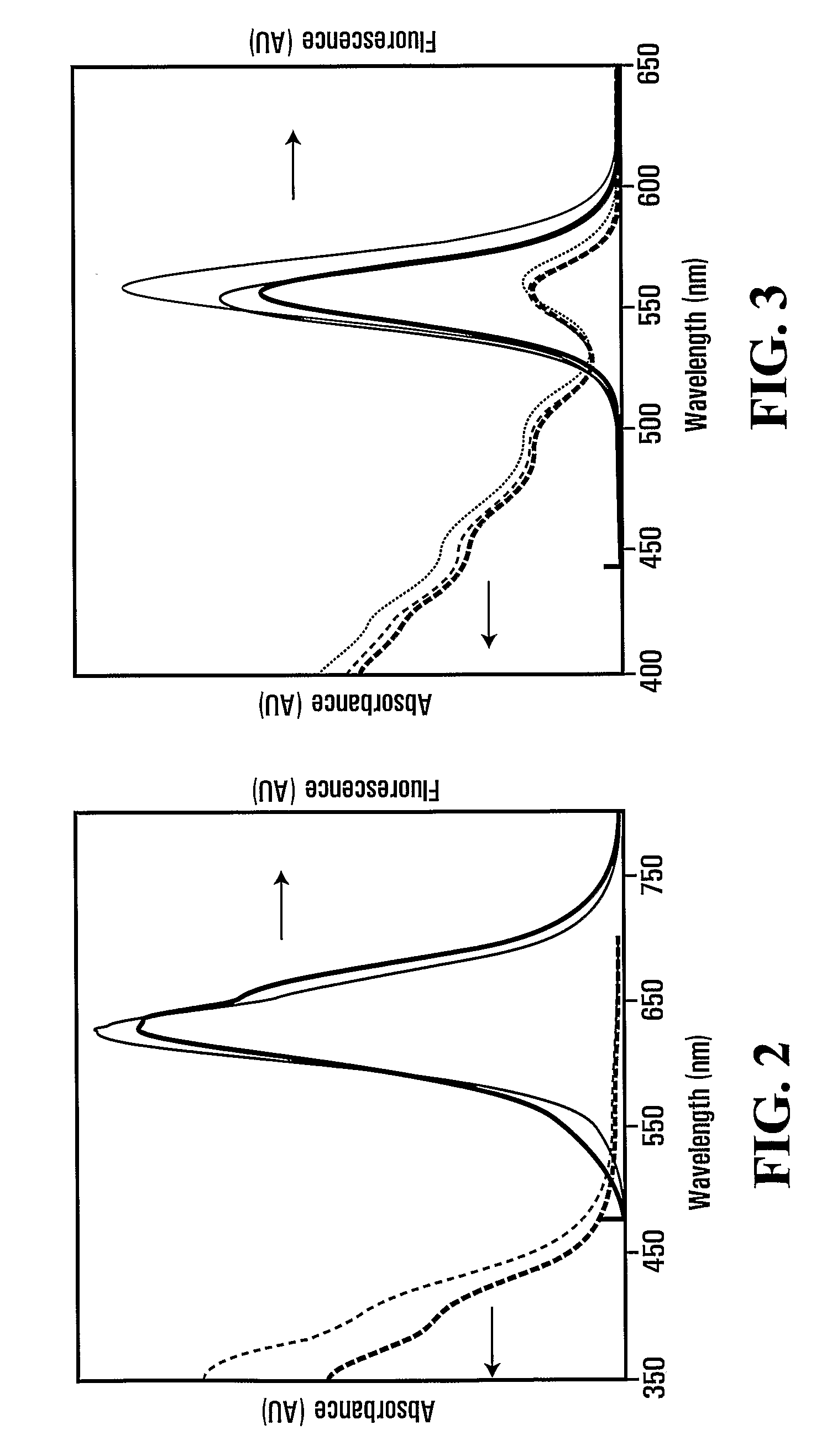
[0083]The fluorescence of the QDs changed from green to red in 90 min. The as-prepared QDs were precipitated with an equivalent amount of 2-propanol, and then re-dissolved in water and precipitated with 2-propanol three more times. Pellets of purified uGSH-CdTe QDs were dried at room temperature in vacuum overnight, and the final product ...
example ii
Synthesis of CdSe / CdS / ZnS QDs
[0084]CdSe / CdS / ZnS QDs capped with trioctylphosphine oxide (TOPO) were synthesized by an organometallic route, based on (with minor modifications) the method disclosed in S. Jun et al., “Synthesis of multi-shell nanocrystals by a single step coating process,”Nanotechnology, 2006, vol. 17, pp. 3892-3896, the entire contents of which are incorporated herein by reference.
[0085]1 mmol of CdO powder (99.99+%) and 2 mmol of octadecylphosphonic acid were mixed in 50 ml of TOA (95%). The mixed solution was degassed and heated to 150° C. with rapid stirring, and then the temperature of the solution was increased up to 300° C. under N2 gas flow. At 300° C., 10 ml of 2.0 M Se in TOP (90%) were quickly injected into the Cd-containing reaction mixture. After 2 minutes, the product was cooled to 50 to 60° C., and an organic sludge was removed by centrifugation (5600 rpm). Ethanol (Fisher™, HPLC grade) was added to the CdSe solution until an opaque flocculation appeare...
PUM
| Property | Measurement | Unit |
|---|---|---|
| molar concentration | aaaaa | aaaaa |
| diameter | aaaaa | aaaaa |
| diameter | aaaaa | aaaaa |
Abstract
Description
Claims
Application Information