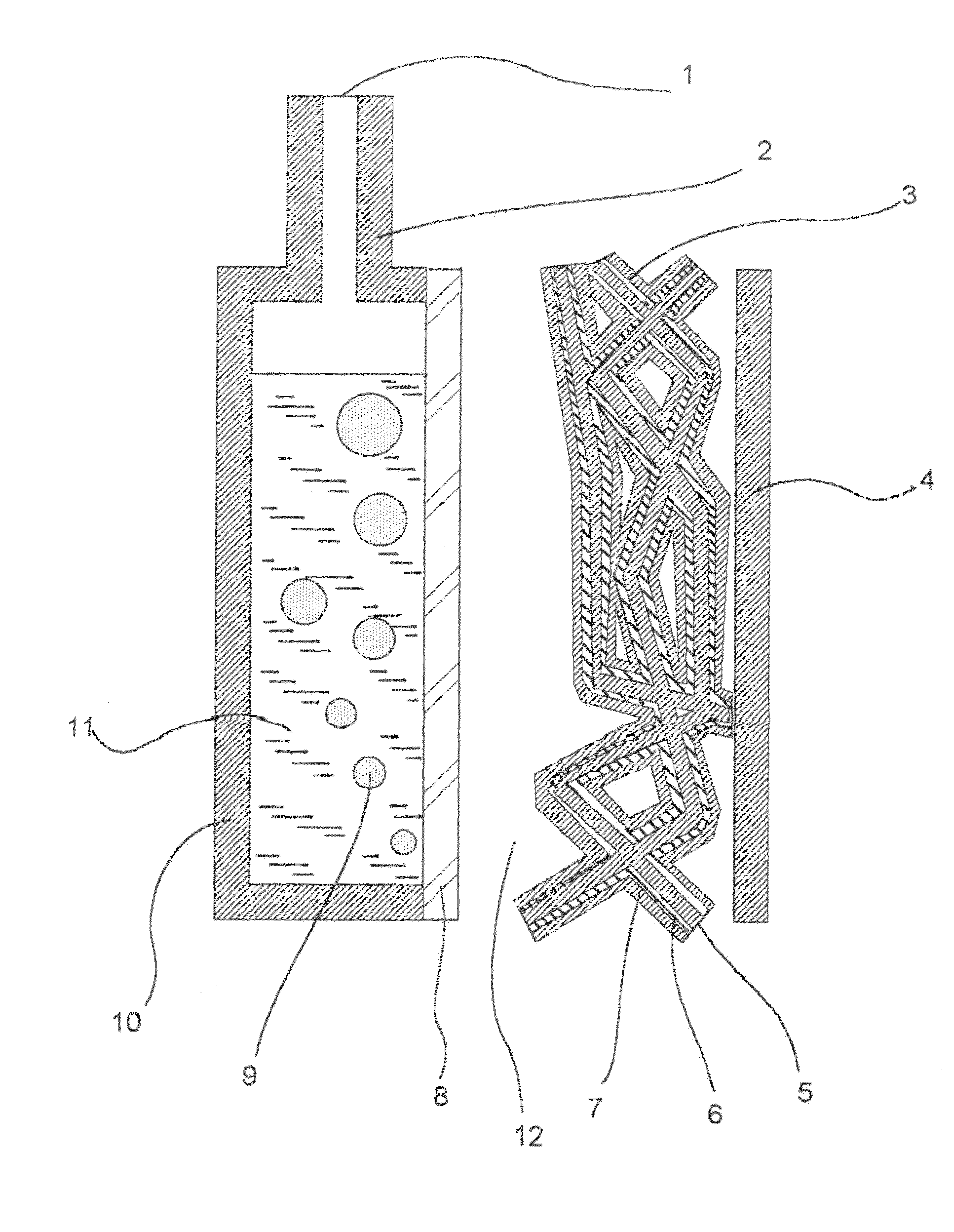
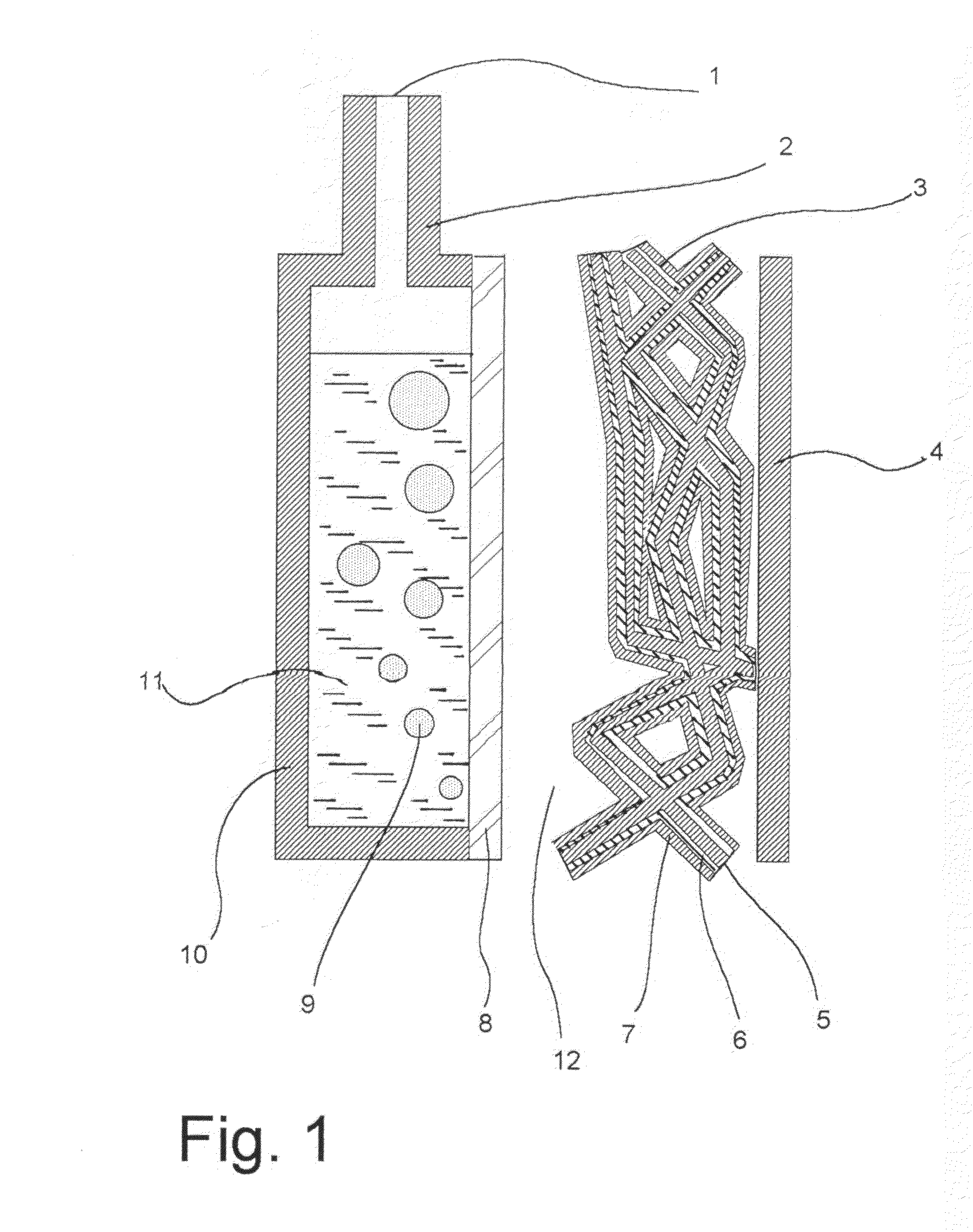
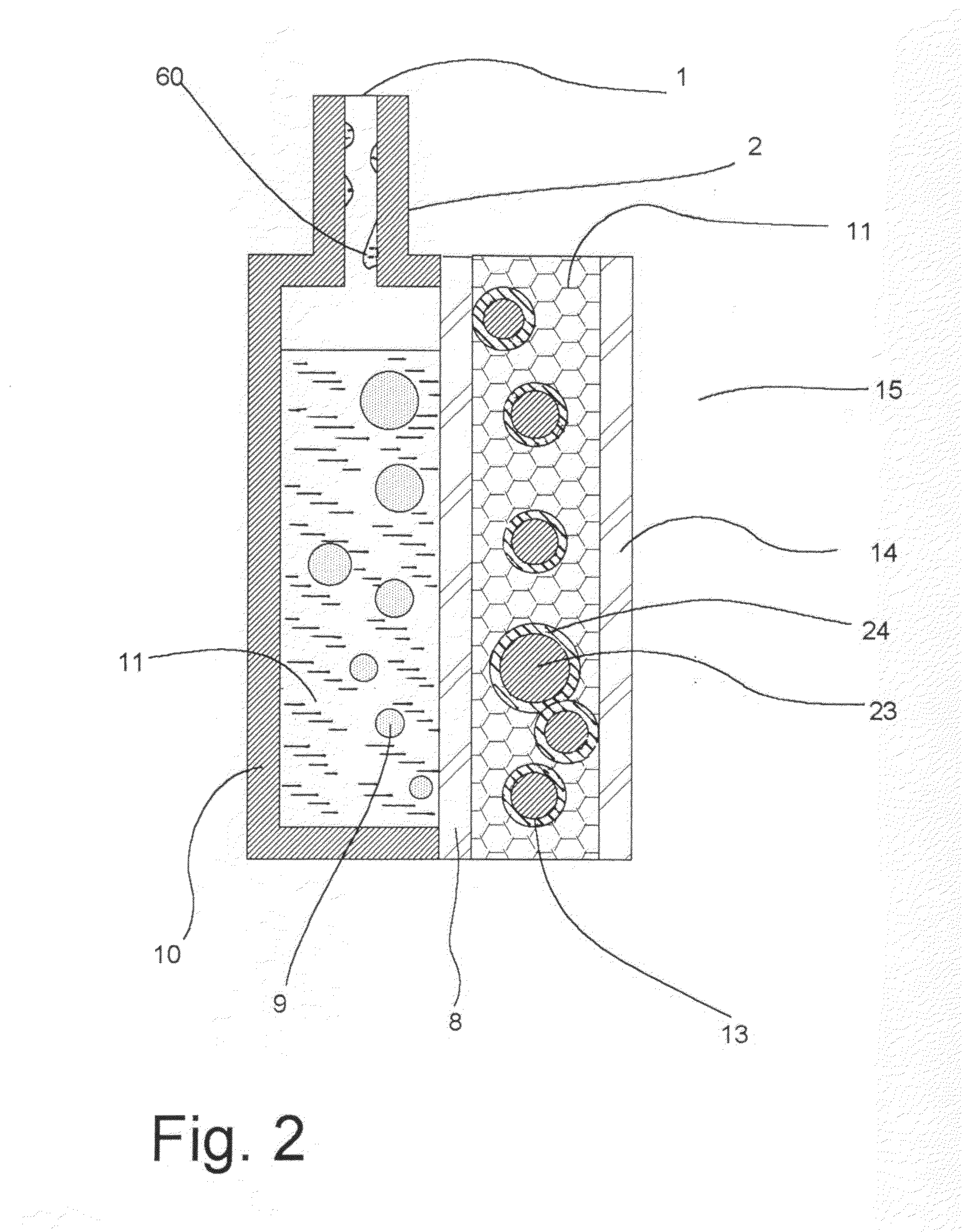
[0005]The invention described herein refers to a portable
catalytic heater in which
fuel vapor and air (or other means of
oxygen supply), are supplied to a catalyst. The catalyst promotes the flameless combustion of the fuel releasing heat. The
liquid fuel is supplied through the use of a selectively permeable membrane, such that only the fuel vapors diffuse through the membrane and are fed to the catalyst. The catalyst is placed on a support that allows for the
diffusion and mixing of reactants such as a
porous fiber felt coated with catalysts. Alternatively, the selectively permeable membrane may support the catalyst. The supply of fuel to the selectively permeable membrane and the exact identity of the membrane serve as a way to regulate the degree of heating provided by the
catalytic heater. The selective molecular
filtration of the fuel through the membrane keeps the
catalytic heater from being contaminated from impurities in the fuel, such as salts. The selective permeability of the membrane to fuels (e.g.
methanol), over the product (i.e. water), keeps the
liquid fuel reservoir from being contaminated with the product and maintains the fuel concentration and a steady rate of
fuel delivery. By containing the fuel behind the selective membrane and using
diffusion to deliver the fuel, the rate is dependent upon the concentration of liquid in contact with the fuel membrane rather than the fuel
vapor pressure. This makes the delivery of fuel and air to the catalyst less sensitive to temperature.
[0006]Another feature of the invention is an additional
coating which protects the combustion catalyst from
contamination and can enhance the catalytic effects. If the
coating has the ability to conduct ions (i.e. protons), it may be used to enhance or lower the
catalytic combustion rate through electrochemical processes on the catalysts (removal / addition of
hydrogen /
proton intermediates to catalytic surface). This may be achieved by inserting two electrodes on either side of the
coating and applying a
voltage across said coating. The coating also has certain permeability to the fuel and the products of the combustion reaction. It serves the purpose of adhering the catalyst powders to the substrate on which they are supported and can limit the catalytic combustion rate serving as yet another regulating mechanism in our invention. The coating can also have an affinity for the fuel, oxidizer, and products to increase the effectiveness of the fuel. The catalytic heater can be incorporated into a
system for various applications. One of the unique features of using a
liquid fuel with the selectively permeable membrane in proximity to the catalytic heater is when the fuel reaches its
boiling point it removes heat from the catalytic
reaction site and subsequently limits the
maximum temperature. The vaporized fuel can be condensed in a
heat exchanger and deliver the thermal output of the heater efficiently. Different mixtures of fuels or a
maximum pressure of the fuel reservoir can be chosen to set the
boiling point of the fuel and hence the
maximum temperature of the heater. This fuel boiling mechanism along with the
back diffusion of
carbon dioxide and
nitrogen can also be used to keep the fuel homogeneous and self purging. By keeping the fuel homogeneous and not in direct contact with catalysts the heater can easily be purged of fuel
contamination by draining the fuel.
[0009]Additional features of this invention are the pressurization of the fuel behind the selectively permeable membrane and its flexibility which enable unique passive controls of the
diffusion of fuel and air. Temperature selective diffusion through the membrane can also be used to limit or accelerate the
fuel delivery. Also, the flexibility of the polymers and rubber materials used in this invention permits flexibility in packaging into a wide variety of applications such as apparel, blankets, machinery, dwellings, shipping containers, storage containers,
insect attractants,
humidifiers, and perfume generators.Prior Art

