

Stents having controlled elution
a technology of elution and stents, which is applied in the direction of prosthesis, extracellular fluid disorder, drug compositions, etc., can solve the problems of inability to optimize the thickness of burs, inability to access difficult lesions, and flexibility of deployment, so as to minimize the intrusion into the vessel wall and facilitate deploymen
- Summary
- Abstract
- Description
- Claims
- Application Information
AI Technical Summary
Benefits of technology
Problems solved by technology
Method used
Image

Examples
example 1
[0256]This example illustrates embodiments that provide a coated coronary stent, comprising: a stent framework and a rapamycin-polymer coating wherein at least part of rapamycin is in crystalline form and the rapamycin-polymer coating comprises one or more resorbable polymers.
[0257]In these experiments two different polymers were employed:[0258]Polymer A: −50:50 PLGA-Ester End Group, MW˜19 kD, degradation rate ˜1-2 months[0259]Polymer B: −50:50 PLGA-Carboxylate End Group, MW˜10 kD, degradation rate ˜28 days
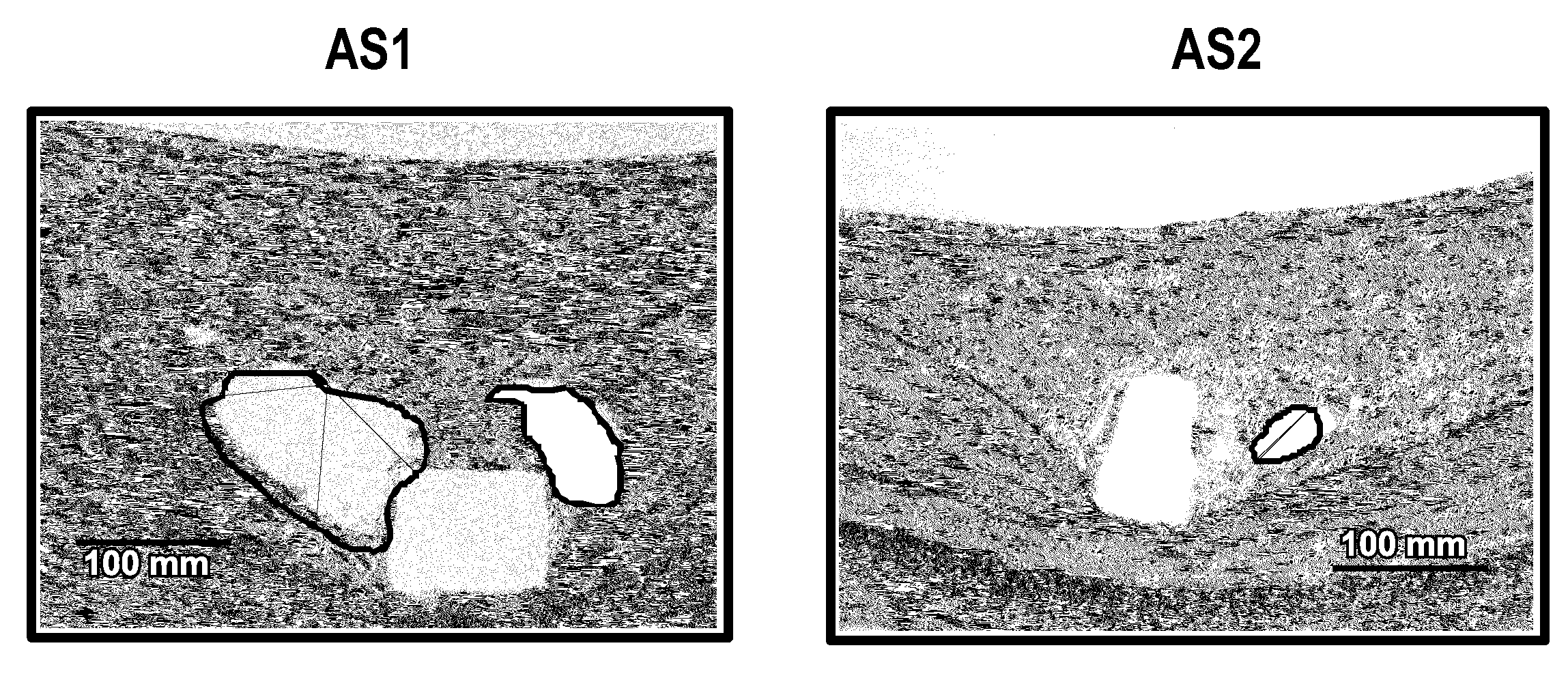
[0260]Metal stents were coated as follows:[0261]AS1: Polymer A / Rapamycin / Polymer A / Rapamycin / Polymer A[0262]AS2: Polymer A / Rapamycin / Polymer A / Rapamycin / Polymer B[0263]AS1 (B) or AS1(213): Polymer B / Rapamycin / Polymer B / Rapamycin / Polymer B[0264]AS1b: Polymer A / Rapamycin / Polymer A / Rapamycin / Polymer A[0265]AS2b: Polymer A / Rapamycin / Polymer A / Rapamycin / Polymer B
example 2
[0266]The presence and or quantification of the Active agent crystallinity can be determined from a number of characterization methods known in the art, but not limited to, XRPD, vibrational spectroscopy (FTIR, NIR, Raman), polarized optical microscopy, calorimetry, thermal analysis and solid-state NMR.
X-Ray Diffraction to Determine the Presence and / or Quantification of Active Agent Crystallinity
[0267]Active agent and polymer coated proxy substrates are prepared using 316L stainless steel coupons for X-ray powder diffraction (XRPD) measurements to determine the presence of crystallinity of the active agent. The coating on the coupons is equivalent to the coating on the stents described herein. Coupons of other materials described herein, such as cobalt-chromium alloys, may be similarly prepared and tested. Likewise, substrates such as stents, or other medical devices described herein may be prepared and tested. Where a coated stent is tested, the stent may be cut length...
example 3
Determination of Bioabsorbability / Bioresorbability / Dissolution Rate of a Polymer Coating a Device
Gel Permeation Chromatography In-Vivo Weight Loss Determination
[0281]Standard methods known in the art can be applied to determine polymer weight loss, for example gel permeation chromatography and other analytical techniques such as described in Jackson et al., “Characterization of perivascular poly(lactic-co-glycolic acid) films containing paclitaxel”Int. J. of Pharmaceutics, 283:97-109 (2004), incorporated in its entirety herein by reference.
[0282]For example rabbit in vivo models as described above are euthanized at multiple time points (t=1 day, 2 days, 4 days, 7 days, 14 days, 21 days, 28 days, 35 days n=5 per time point). Alternatively, pig in vivo models as described above are euthanized at multiple time points (t=1 day, 2 days, 4 days, 7 days, 14 days, 21 days, 28 days, 35 days n=5 per time point). The stents are explanted, and dried down at 30° C. under a stream of gas to compl...
PUM
| Property | Measurement | Unit |
|---|---|---|
| Temperature | aaaaa | aaaaa |
| Temperature | aaaaa | aaaaa |
| Fraction | aaaaa | aaaaa |
Abstract
Description
Claims
Application Information