Electric double layer capacitor

a double-layer capacitor and capacitor technology, applied in the direction of conductors, ceramicware, applications, etc., can solve the problems of insufficient charge-discharge characteristics at rapid and high current, difficult to produce polarizable electrodes having a high electrode density, and difficult to sufficiently reduce internal resistance or impedance by carbon fiber networks. , to achieve the effect of increasing current load, rapid charge, and stable supply of electric power

Inactive Publication Date: 2010-11-25
SHOWA DENKO KK
View PDF4 Cites 25 Cited by
  • Summary
  • Abstract
  • Description
  • Claims
  • Application Information

AI Technical Summary

Benefits of technology

[0018]The electric double layer capacitor of the present invention can be rapidly charged at a high current in wide temperature environments ranging from low to high temperatures, ensures stable supply of electric power corresponding to an increase in current load at low temperatures, and does not induce heat generation, ignition, etc., and therefore has high safety.
[0019]The electric double layer capacitor of the present invention is suitably applicable to portable electrical and electronic equipment, electric vehicles, etc., which are used in wide temperature environments ranging from low to high temperatures. The capacitor is also applicable to non-contact charging systems etc.

Problems solved by technology

However, the microwave-activated carbon nanotubes and fullerene used in the electric double layer capacitor proposed in Patent Document 2 have a high BET specific surface area of about 3500 m2 / g, and it is therefore difficult to produce polarizable electrodes having a high electrode density.
In the electric double layer capacitor proposed in Patent Document 3, the very thin carbon fibers made of a phenol resin have low electrical conductivity, and it is therefore difficult to sufficiently reduce the internal resistance or impedance by the carbon fiber network.
Thus, charge-discharge characteristics are insufficient at rapid and high current.
Moreover, as for the electric double layer capacitor proposed in Patent Document 1 or 4, it is confirmed that satisfactorily high output capacitance and low internal resistance are achieved at high temperatures; however, at low temperatures, the output capacitance does not reach a sufficiently high level, and the internal resistance is high.

Method used


Image

  • Electric double layer capacitor
  • Electric double layer capacitor
  • Electric double layer capacitor

Examples


example 1

Carbon Fibers A

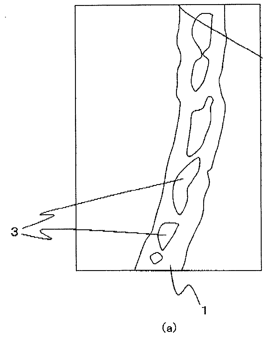
[0139]Vapor-grown carbon fibers produced by a standard method (mean fiber diameter: about 20 nm, length: about 10000 nm; manufactured by Showa Denko K.K.) were mixed with potassium hydroxide (purity: 95.0%; manufactured by Toagosei Co., Ltd.) in an amount 4.0 times by mass the amount of fibers, distilled water and ethanol. The mixture was put in a nickel container, and the container was placed in a batch type electric furnace. In the N2 atmosphere, the temperature was increased to 400° C. at a heating rate of 5° C. / min. and maintained for 30 minutes. Subsequently, the temperature was increased to 750° C. and maintained for 15 minutes. Finally, the container was allowed to stand in the furnace until the temperature was 100° C. or less. The container was taken out from the furnace into the air, and 1N-hydrochloric acid was added to the reaction product for neutralization. The neutralized product was washed twice with boiling 0.1N-hydrochloric acid to remove metal impuri...

example 2

Carbon Fibers C

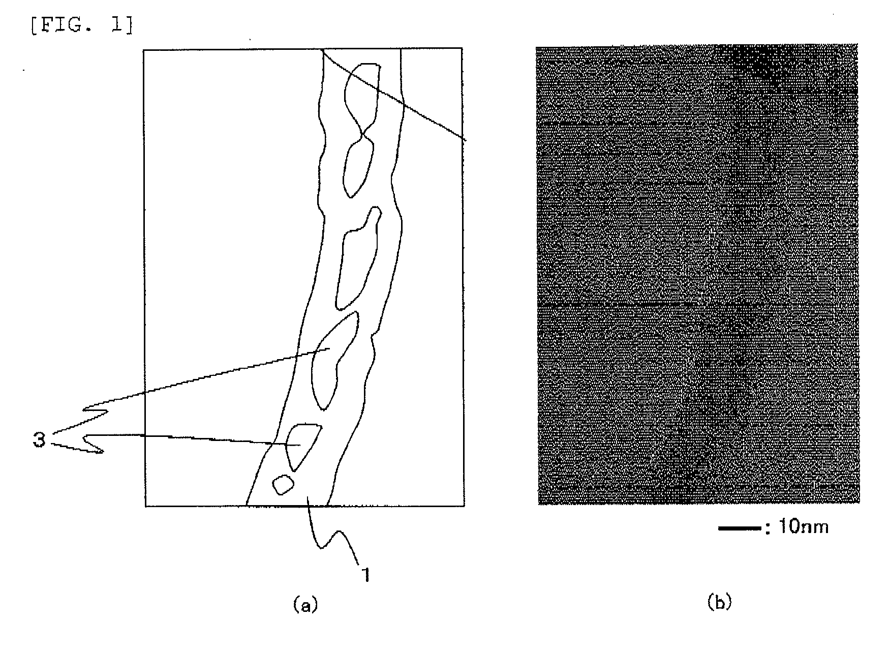
[0140]Vapor-grown carbon fibers produced by a standard method (mean fiber diameter: about 150 nm, length: about 9000 nm; manufactured by Showa Denko K.K.) were baked at 1000° C. The carbon fibers after baking had a mean fiber diameter of about 150 nm and a length of about 9000 nm. The baked carbon fibers were mixed with potassium hydroxide (purity: 95.0%; manufactured by Toagosei Co., Ltd.) in an amount 4.0 times by mass the amount of fibers, distilled water and ethanol. The mixture was put in a nickel container, and the container was placed in a batch type electric furnace. In the N2 atmosphere, the temperature was increased to 400° C. at a heating rate of 5° C. / min. and maintained for 30 minutes. Subsequently, the temperature was increased to 750° C. and maintained for 15 minutes. Finally, the container was allowed to stand in the furnace until the temperature was 100° C. or less. The container was taken out from the furnace into the air, and 1N-hydrochloric acid wa...

example 3

Electric Double Layer Capacitor A

[0148]An A1085 aluminum foil having a thickness of 30 μm was prepared. 40 parts by mass of a polymer of cellulose cross-linked with acrylamide (an ion-permeable compound; TG-DTA pyrolysis initiation temperature: 275° C.), 40 parts by mass of acetylene black (carbon fine particles; primary particle diameter: 40 nm), and 20 parts by mass of water were mixed and kneaded to obtain a paste.

[0149]Using an applicator (gap: 10 μm), the paste was applied to the aluminum foil by the cast method, followed by drying in air at 180° C. for 3 minutes. Thus, a coating that is conductive adhesive layer containing the ion-permeable compound and the carbon fine particles was formed on the aluminum foil.

[0150]In 65 parts by mass of activated carbon A, 5 parts by mass of the carbon fibers A were dispersed so that aggregates having a diameter of 10 μm or more were not formed. A binder and solvent were added thereto and kneaded to obtain a paste.

[0151]The paste was applied...


PUM

PropertyMeasurementUnit
diameteraaaaaaaaaa
BET specific surface areaaaaaaaaaaa
pore sizeaaaaaaaaaa

Abstract

Disclosed is an electric double layer capacitor having a positive polarizable electrode and a negative polarizable electrode, each of the positive and negative polarizable electrodes having a polarizable electrode layer, the positive polarizable electrode layer containing carbon fibers P and activated carbon P, the negative polarizable electrode layer containing carbon fibers N and activated carbon N, wherein at least one of the carbon fibers P and carbon fibers N has at least one peak in the range of 1 to 2 nm in a pore distribution determined by BJH analysis using a nitrogen adsorption method, and the sum total of BET specific surface areas of the activated carbon P and the carbon fibers P is larger than the sum total of BET specific surface areas of the activated carbon N and the carbon fibers N.

Description

TECHNICAL FIELD[0001]The present invention relates to an electric double layer capacitor. More specifically, the present invention relates to an electric double layer capacitor that can be rapidly charged at a high current in wide temperature environments ranging from low to high temperatures, that ensures stable supply of electric power corresponding to an increase in current load at low temperatures, that does not induce heat generation, ignition, etc., and therefore has high safety, and that is applicable to non-contact charging systems etc.BACKGROUND ART[0002]Electric double layer capacitors have the features that they have along life because they are not accompanied by chemical reactions, that are capable of rapid charging and discharging at a higher current when compared to secondary batteries, and that are resistant to over-charging and over-discharging.[0003]Taking advantages of these features, electric double layer capacitors have mainly been used, for example, in memory ba...

Claims


Application Information

Patent Timeline
Patent Type & Authority Applications(United States)
IPC IPC(8): H01G9/058D01F9/12H01B1/04H01G11/32H01G11/40
CPCB82Y30/00H01G11/40C04B35/6268C04B35/62844C04B35/83C04B38/0054C04B2235/5248C04B2235/526C04B2235/5264C04B2235/5284C04B2235/5296C04B2235/5409C04B2235/5436D01D5/247D01F9/12Y02E60/13Y02T10/7022C04B35/62675H01G11/32C04B38/0074Y02T10/70
Inventor NANBA, YOUICHITANAKA, MASAKOMORI, TAKASHI
Owner SHOWA DENKO KK
Why Eureka
Try Eureka