Method for producing crystallographically oriented ceramic

a crystallographic orientation and ceramic technology, applied in the direction of crystal growth process, polycrystalline material growth, coating, etc., can solve the problems of difficult to produce thick films, low productivity, and difficult to orient piezoelectric thin films seed crystals in the 100 degree range, so as to increase the degree of orientation of lead-containing materials. , the effect of easy orientation

Inactive Publication Date: 2011-01-20
NGK INSULATORS LTD
View PDF16 Cites 9 Cited by
  • Summary
  • Abstract
  • Description
  • Claims
  • Application Information

AI Technical Summary

Benefits of technology

[0016]The method for producing a crystallographically oriented ceramic of the present invention enables us to more easily produce a crystallographically oriented ceramic with a higher degree of orientation. The exact reason for this is unclear. The reason may be as follows: It is speculated that, for example, although a lead-containing material is not easily formed into a polyhedral shape, the additional material containing lithium and boron probably functions to grow crystals of the lead-containing material for the matrix layer in a polyhedral shape (e.g., a cube). Furthermore, it is speculated that the crystals of the material for the matrix layer are grown on the basis of the crystal orientation of the template layer, so that the ceramic is more easily oriented. Moreover, it is possible to increase the degree of orientation of the lead-containing material by a simple method in which the matrix layer is formed on the template layer having uniform crystal orientation and fired.

Problems solved by technology

However, the production method described in Patent Document 1 disadvantageously has difficulty in the production because it is necessary to produce the seed crystals of the piezoelectric thin film by sputtering, which has a relatively low productivity, and to perform hydrothermal synthesis to form a thick film.
Furthermore, the method has a problem in which the seed crystals of the piezoelectric thin film are not easily oriented in the (100) or (111) plane.
In the production method described in Patent Document 2, it is difficult to produce a thick film because of the crystal growth by sputtering or chemical vapor deposition (CVD).
Furthermore, it is difficult to form a thick film.

Method used


Image

  • Method for producing crystallographically oriented ceramic
  • Method for producing crystallographically oriented ceramic
  • Method for producing crystallographically oriented ceramic

Examples


example 1

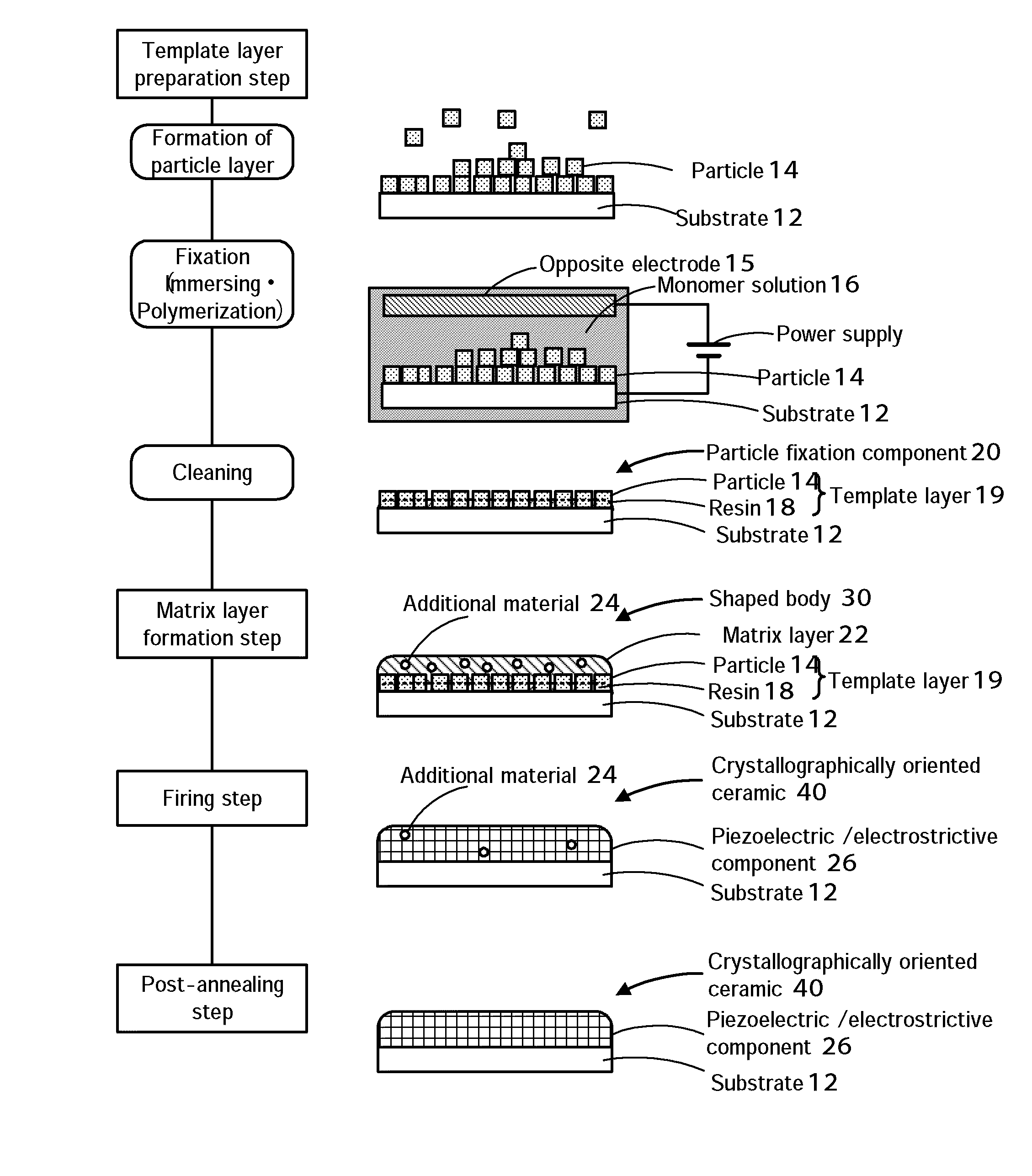
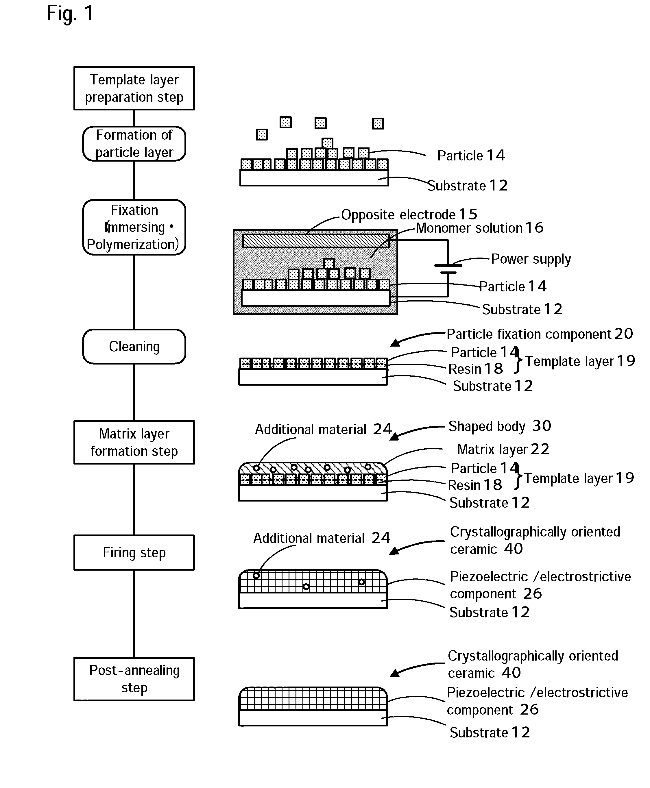
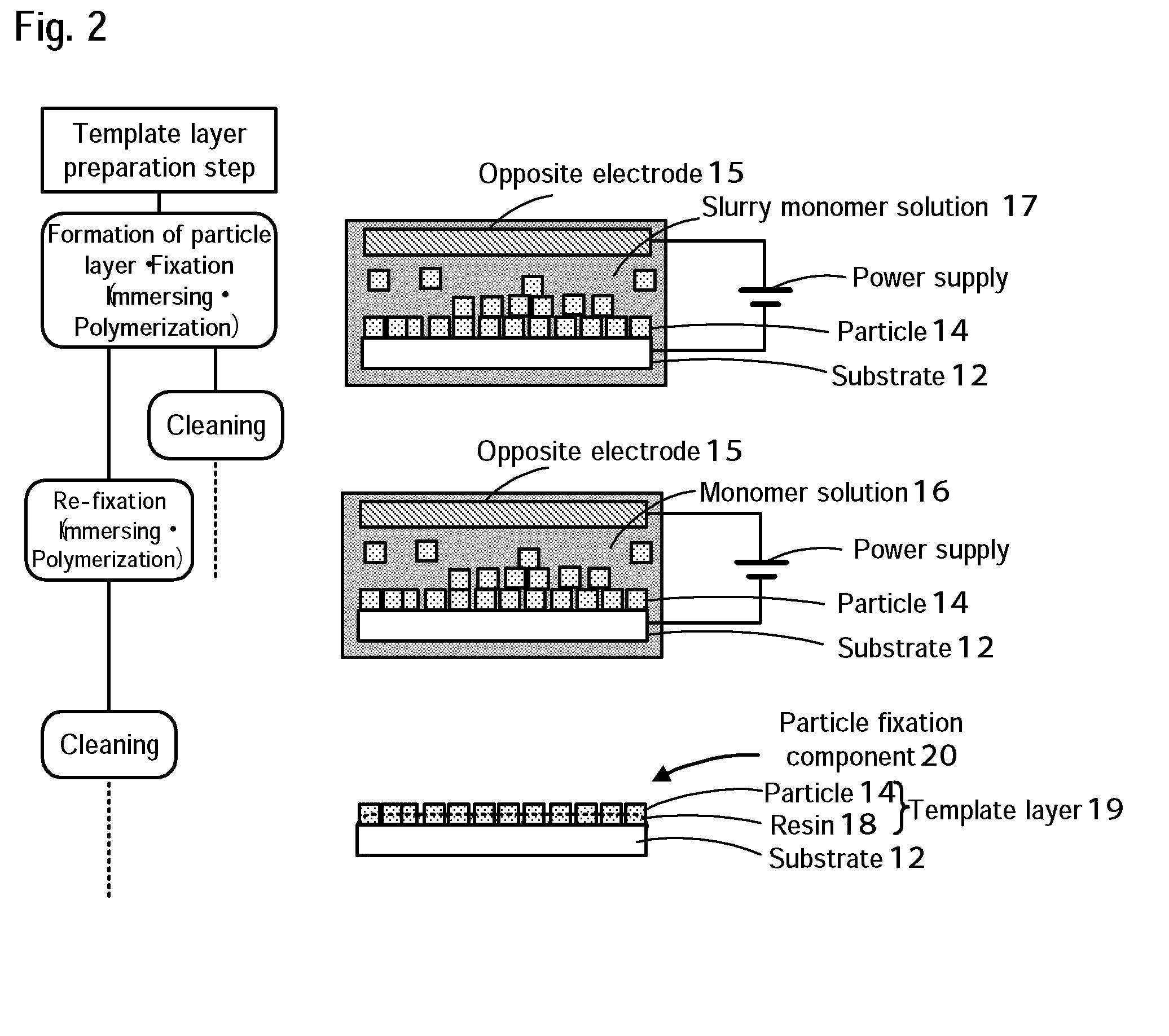
Template Layer Preparation Step

[0045]A platinum substrate having a size of 10 mm×10 mm and a thickness of 0.5 mm was used as a substrate. Materials for a template layer were an aqueous lead solution containing lead acetate trihydrate (manufactured by Kanto Chemical Co., Inc.), ethylenediaminetetraacetic acid (manufactured by Kanto Chemical Co., Inc.), and potassium hydroxide (manufactured by Kanto Chemical Co., Inc.), an aqueous zirconium solution containing zirconium oxychloride octahydrate (manufactured by Kanto Chemical Co., Inc.), an aqueous solution of titanium chloride (manufactured by Wako Pure Chemical Industries, Ltd.), and an aqueous solution of potassium hydroxide (manufactured by Kanto Chemical Co., Inc). A raw material solution was prepared so as to have a molar ratio of Pb:Zr:Ti=1.1:0.7:0.3. Into a 100-mL stainless-steel pressure vessel having an inner wall lined with polytetrafluoroethylene, 30 mL of the raw material solution was charged. A hydrothermal synthesis trea...

example 2

[0048]A LiBO2-containing 20PMN-80PZT paste was prepared in the same procedure as in Example 1. A (100)-oriented single-crystal strontium titanate (SrTiO3) substrate provided with (100) strontium ruthenate (SrRuO3) formed as a bottom electrode was used. The resulting paste was applied by spin coating onto the SRO / STO substrate to form a film. The film was degreased and fired. The conditions of the film formation, calcination, and firing were the same as in Example 1. The resulting crystallographically oriented ceramic was defined as a ceramic obtained in Example 2.

example 3

[0049]Cube-shaped PZT particles the same as in Example 1 were mixed with a butyral-based binder (BM-2, manufactured by Sekisui Chemical Co., Ltd.), a solvent (an equal volume mixture of toluene and isopropyl alcohol), and a plasticizer (DOP) to form a slurry. The slurry was formed into a tape having a thickness of about 2 μm in the dry state by a doctor blade method. A LiBO2-containing 20PMN-80PZT powder was formed into a tape having a thickness of about 2 μm in the dry state by the same process. These tapes were cut into tape pieces. The tape pieces including only the PZT particles were used as template layers. The tape pieces including the LiBO2-containing 20PMN-80PZT were used as matrix layers. The tape pieces were alternately stacked to form a laminate. The laminate was press-bonded under heat and pressure in order to promote the adhesion of the stacked tape pieces. The resulting laminate was degreased in air at 600° C. and then fired at 1000° C. for 3 hours. The resulting cryst...


PUM

PropertyMeasurementUnit
thicknessaaaaaaaaaa
grain sizeaaaaaaaaaa
temperatureaaaaaaaaaa

Abstract

A method for producing a crystallographically oriented ceramic according to the present invention includes a preparation step of preparing a template layer having uniform crystal orientation in a predetermined direction, a formation step of forming a shaped body including a matrix layer arranged on the template layer, the matrix layer being composed of a mixed material that contains a lead-containing material and an additional material containing lithium and boron, and a firing step of firing the shaped body formed in the formation step at a predetermined firing temperature. Furthermore, after the firing step, a post-annealing step of heating the shaped body to remove lithium and boron may be included.

Description

BACKGROUND OF THE INVENTION[0001]1. Field of the Invention[0002]The present invention relates to a method for producing a crystallographically oriented ceramic, and more specifically, it relates to a method for producing a crystallographically oriented ceramic used for a piezoelectric / electrostrictive component.[0003]2. Description of the Related Art[0004]Hitherto, regarding a method for producing a crystallographically oriented ceramic, piezoelectric thin films as typified by thin films composed of lead zirconate titanate (hereinafter, referred to as “PZT”) have been formed by depositing films using, for example, physical vapor deposition (PVD) such as sputtering, chemical vapor deposition (CVD), and a sol-gel method and firing the films. In the vapor phase deposition, however, it is difficult to increase the film thickness to, for example, 1 μm or more. The use of the sol-gel method sometimes causes a reduction in density, thus failing to provide satisfactory piezoelectric propert...

Claims


Application Information

Patent Timeline
Patent Type & Authority Applications(United States)
IPC IPC(8): C04B35/64
CPCC04B35/493C04B35/62685C04B2235/3203C04B2235/3206C04B2235/3251C04B2235/3279C04B2235/3409C04B2235/445C04B2235/52C04B2235/6025C04B2235/656C04B2235/662C04B2235/77C04B2235/787C09D5/4476C30B28/04C30B29/22H10N30/04H10N30/074
Inventor KOIZUMI, TAKAAKIKATSUNO, TAKUYA
Owner NGK INSULATORS LTD
Why Eureka
Try Eureka