[0014]The thermal paths can utilize high thermal
conductive materials, which may also be
electrically conductive, such as solder in SSIs,
copper used in wiring and TSVs, or simply adding thermal interconnections for improved
heat transfer and / or
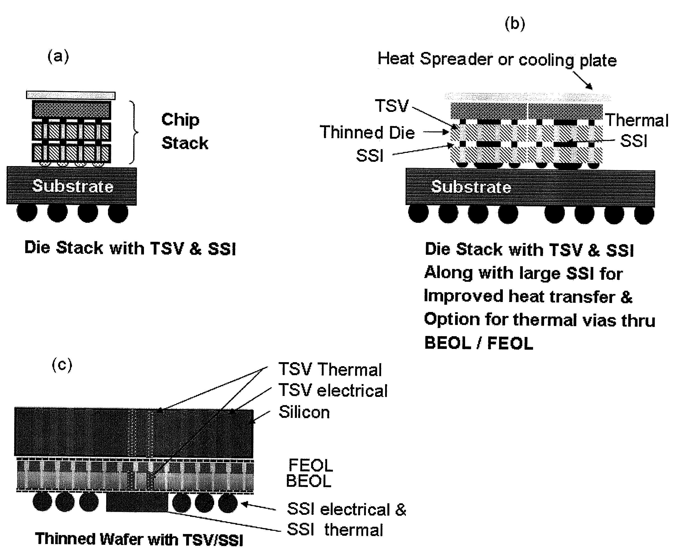
mechanical integrity. The thermal paths can also utilize materials having high
thermal conductivity but which are electrically insulating, such as BeO, SiC, carbon nanotubes, etc. Thus, to aide in removing heat from a die stack, thermal vias can be added to an ILD (inter-layer-dielectric), and underfills with improved
thermal conductivity can be added between silicon strata levels and between other interconnections, such as solder interconnections, Cu—Cu and other electrical connections. The area of a conductor between silicon strata levels can be increased. Thus, the use of thermal TSVs and SSIs can aide in heat removal from a die stack, and the use of a larger SSI area also increases heat removal.
[0016]The proper choice of materials for
interconnection can help avoid soft errors due to subatomic or cosmic particles that can cause errors in the resulting circuits. The use of low alpha solders such as alloys of AuSn, In, Sn, SnCu, In—Ni—Cu, SnAg or other alloys can service these interconnections. Large blocks of solder are used for thermal interconnection along with small interconnections of solder microbumps for signals and small or intermediate size
diameter bumps for power. Bumps can be taylored for electrical, thermal, power and
mechanical integrity. Areas over macros can have mechanical / thermal pads or an array of bumps, or other shapes, and the option of thermal vias in some or all of the BEOL and FEOL where it aids
thermal conduction and fits an overall design.
Adhesive underfill or no-flow underfills and / or combinations with seal bands can aide in
mechanical integrity and
corrosion protection of interconnections.
[0017]Ball-limiting
metallurgy (BLM) is used for each silicon layer to provide a grid of power feed throughs at one or more voltages to support power distribution from TSV dense regions to
macro regions lacking TSV's. A dielectric can be provided over power and / or ground distribution wiring to create a micro connection area on one side of an SSI and the same for the other side to create a large current carrying capability without added fat wire
layers, thus keeping costs down in power distribution while maintaining efficient circuit dense regions. This can be accomplished by interconnecting wiring connections to the pads connected to solder bumps to create a wiring distribution or mesh to provide a
power grid o which can support the application
voltage levels and
system requirements.
[0031]According to a further aspect of the invention, the
silicon interposer is larger in horizontal directions than said die stack, wherein said substrate has a different coefficient of
thermal expansion than said die stack, and wherein stresses resulting from attaching said die stack to said substrate are reduced.
[0034]According to a another aspect of the invention, there is provided a silicon-silicon die stack structure comprising a substrate, a plurality of thin silicon die wafer
layers disposed on said substrate with a
high density of vertical through-silicon-vias (TSVs) through the wafer
layers for electrical
interconnectivity, a silicon-silicon interconnection between each wafer layer, said silicon-silicon interconnection including a plurality of metallic interconnection and thermal paths surrounded by an
adhesive dielectric layer, wherein said silicon-silicon interconnections further include solder interconnections of various size to provide
high density arrays of signals in vertical paths and areas for
thermal transport and power feed through, and underfills with improved
thermal conductivity between silicon strata levels and between other interconnections for improved mechanical integrity and
corrosion protection of interconnections, wherein larger blocks of solder are used for thermal interconnection, intermediate size
diameter blocks of solder are used for
power transmission, and smaller blocks of solder are used for
signal transmission.
[0040]According to a further aspect of the invention, the
silicon interposer has a larger horizontal dimension than the silicon die wafers in the stack, wherein said substrate has a different coefficient of
thermal expansion than said die stack, and wherein stresses resulting from attaching said die stack to said substrate are reduced.

