Carbon nanofiber, producing method and use of the same

a carbon nanofiber and nanofiber technology, applied in the direction of catalyst activation/preparation, non-conductive materials with dispersed conductive materials, metal/metal-oxide/metal-hydroxide catalysts, etc., can solve the problems of high manufacturing cost, poor influence on the properties of resin materials, and increase in mechanical properties of composite materials such as strength and the like. , to achieve the effect of high heat conductivity, high electric conductivity and low cos

Inactive Publication Date: 2011-05-05
SHOWA DENKO KK
View PDF18 Cites 13 Cited by
  • Summary
  • Abstract
  • Description
  • Claims
  • Application Information

AI Technical Summary

Benefits of technology

[0043]According to the present invention, a carbon nanofiber suitable as electric conductive filler for resin can be obtained. Since the carbon nanofiber in the present invention can give high electric conductivity and high heat conductivity with an added amount smaller than in the past, an electrically conductive or thermally conductive resin composite material with a smaller amount of impurity metal element can be obtained inexpensively. Moreover, as compared with the carbon nanotube, the carbon nanofiber in the present invention has high surface activity, and it is also suitable as a catalyst carrier such as a fuel cell and the like or an adsorption agent for methane gas, hydrogen gas and the like.

Problems solved by technology

The conductive filler added in a large quantity gives a bad influence to the properties of the resin material, and original characteristics of the resin might not be exerted in the prepared composite material.
If there are many impurities in the resin composite material, there is a problem that mechanical properties of the composite material such as strength and the like are extremely lowered because of invitation in decomposition of the resin by the impurities in molding and the like.
However, since the fluidized vapor phase method requires a high-temperature reaction field in general, a manufacturing cost is raised.
Since the carbon fiber obtained by the fluidized vapor phase method has many defects in a graphite layer and has a problem that without heat treatment at a high temperature for graphitization after the generation of the carbon nanofiber, electric conductivity does not emerge even if being added to a resin or the like as filler.
Thus, with the fluidized vapor phase method, it is difficult to inexpensively produce a carbon nanofiber having desired properties.
Moreover, if this method is to be industrially utilized, since a platy substrate surface area can not be ensured unless a number of substrates are arranged, not only that device efficiency is low but also many processes such as supporting of the catalytic metal on the substrate, synthesis of the carbon nanotube, collection of the carbon nanotube from the substrate and the like are needed, which is not economical, and industrial utilization has not been realized yet.
However, with this method, a catalyst carrier is un-avoidably mixed in a carbon nanofiber or a carbon nanotube, and it is difficult to obtain a carbon nanofiber or a carbon nanotube with high purity.
As a method for reducing the amount of impurities in the carbon nanofiber or the carbon nanotube, (1) a method of heat treatment at a high temperature; and (2) a method of washing and removing with acid or base are known, but both of the methods have complicated processes and are not economical.
Particularly, in the washing and removing of the impurities with acid or base, since the catalyst carrier and the catalytic metal in the carbon nanofiber or the carbon nanotube are covered by a carbon overcoat in many cases, it is difficult to fully remove the impurities unless the carbon overcoat is removed by using an oxidizing acid such as nitric acid or by performing partial oxidization.
If an oxidizing acid is used, not only the carbon overcoat on the surface of the carrier or the catalyst but also the carbon nanotube itself might be damaged and might become defective.
The carbon fiber affected by an acid might have lowered electric conductivity or lowered heat conductivity, or dispersibility or filling performance into a resin or the like might be deteriorated.
However, catalyst manufacture by coprecipitation is known to have low efficiency and high cost.
However, since the obtained carbon fiber has a high impurity content, when it is used as filler to a resin, there is a problem that strength of the resin is lowered.

Method used


Image

  • Carbon nanofiber, producing method and use of the same
  • Carbon nanofiber, producing method and use of the same
  • Carbon nanofiber, producing method and use of the same

Examples


example 1

[0123]In methanol, 0.36 part by mass of iron nitrate nonahydrate and 1.00 part by mass of cobalt (II) nitrate hexahydrate were dissolved. Moreover, 0.05 part by mass of ammonium metavanadate and 0.075 part by mass of hexaammonium heptamolybdate tetrahydrate were added and dissolved so as to obtain a catalyst preparation solution.

[0124]The catalyst preparation solution was dripped and mixed with 1 part by mass of gamma-alumina (AKP-G015; made by Sumitomo Chemical Co., Ltd.). After the mixing, it was vacuum-dried at 100 degrees C. for 4 hours. After the drying, it was crushed in a mortar and pestle so as to obtain a catalyst. The catalyst contained 10% by mol of Mo and 10% by mol of V with respect to the total amount of Fe and Co, and 5% by mass of Fe and 20% by mass of Co were supported by the gamma-alumina.

[0125]The weighed catalyst was placed on a quartz boat, and the quartz boat was put in a tubular reactor made by quartz and the vessel was sealed. While a nitrogen gas was made to...

example 2

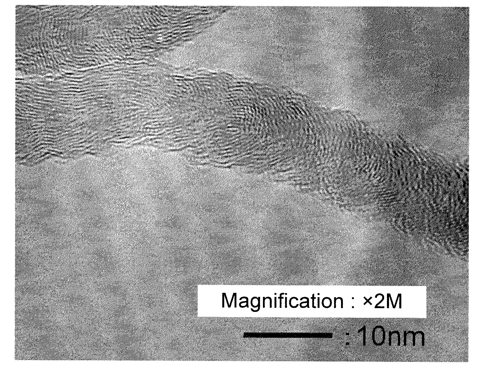
[0128]A catalyst was obtained by the same manner as in Example 1 except that the catalyst preparation recipe was changed to that as shown in Table 1. Using the catalyst, a carbon nanofiber was obtained by the same manner as in Example 1. A carbon nanofiber with low impurity amount was obtained. The result is shown in Table 1. An image observed by the transmission electron microscope of the carbon nanofiber obtained in Example 2 was similar to that in FIG. 1.

examples 3 to 5

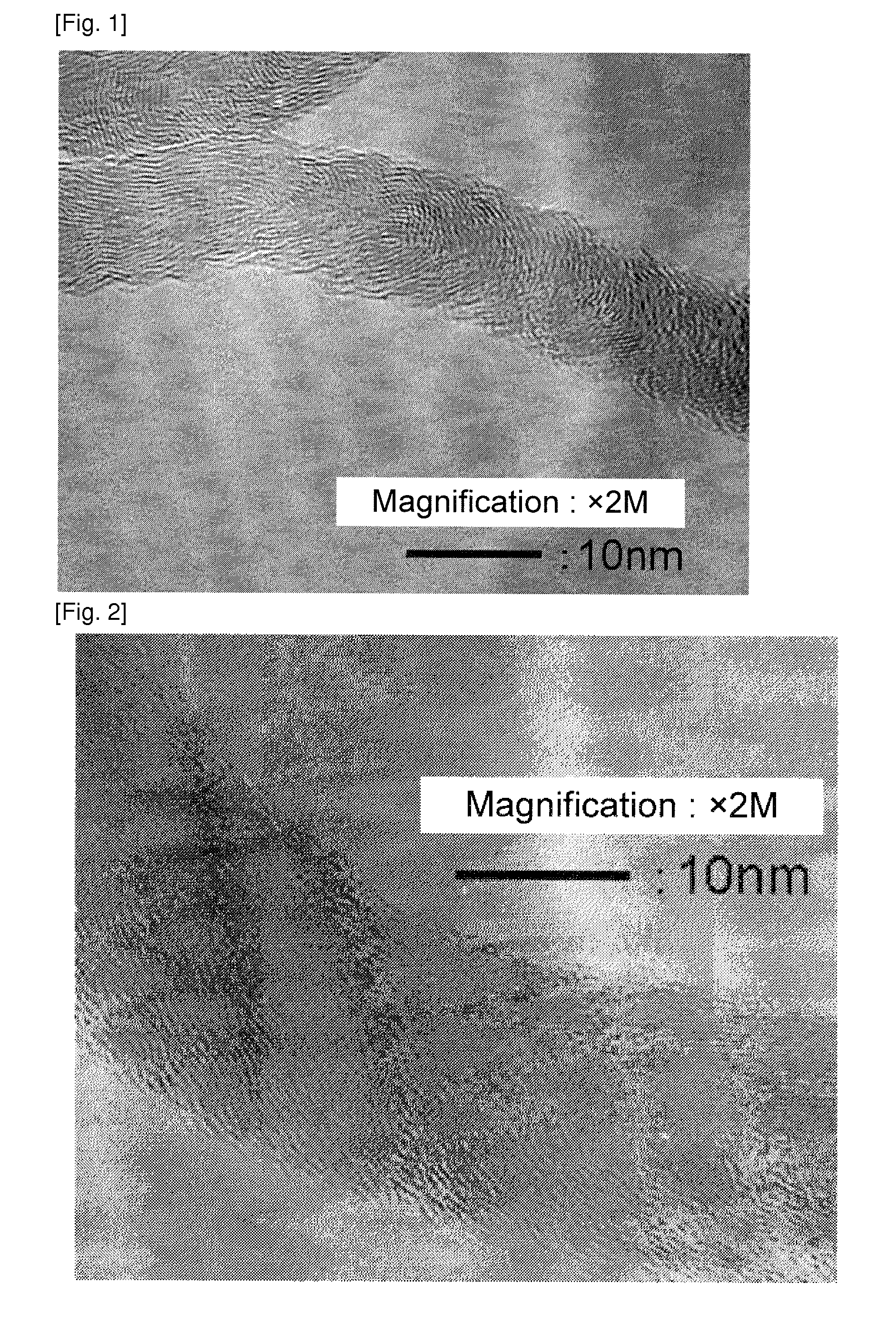
[0129]A catalyst was obtained by the same manner as in Example 1 except the change to the catalyst preparation recipe as shown in Table 1. A carbon nanofiber with a low impurity amount was obtained. The result is shown in Table 1. An image observed by the transmission electron microscope of the carbon nanofiber obtained in Example 3 was shown in FIG. 2. Images observed by the transmission electron microscope of the carbon nanofiber obtained in Examples 4 and 5 were similar to that in FIG. 2.

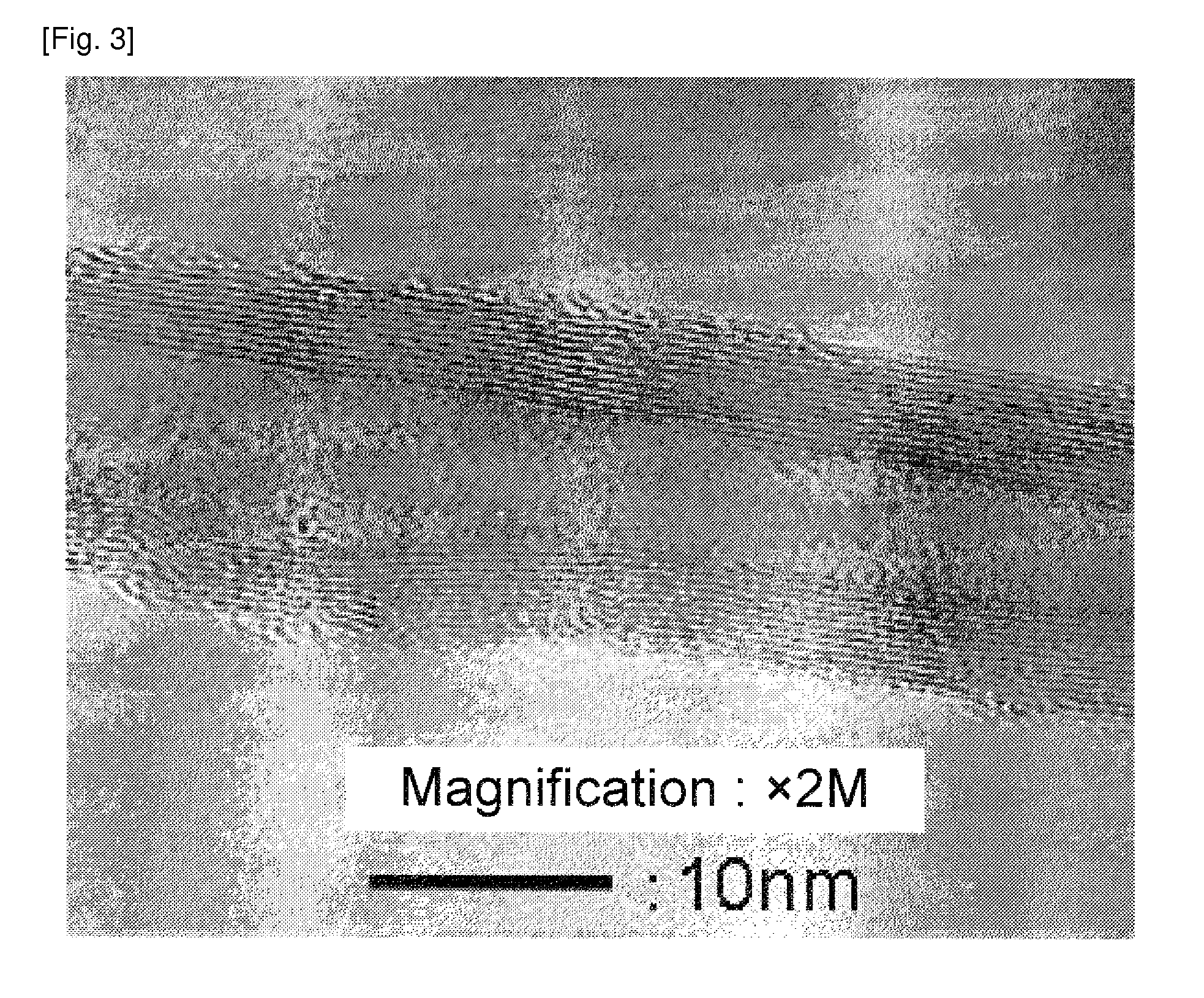
[0130]Since the graphite layer was corrugated or curved, an approximate line was drawn in the vicinity of the carbon nanofiber surface, and an angle formed by the approximate line and the fiber axis was measured, which was approximately 20 to 35 degrees. Most of the carbon nanofiber had hollow portions.


PUM

PropertyMeasurementUnit
diameteraaaaaaaaaa
thicknessaaaaaaaaaa
thicknessaaaaaaaaaa

Abstract

A catalyst for producing a carbon nanofiber is obtained by dissolving or dispersing [I] a compound containing Fe element; [II] a compound containing Co element; [III] a compound containing at least one element selected from the group consisting of Ti, V, Cr, and Mn; and [IV] a compound containing at least one element selected from the group consisting of W and Mo in a solvent to obtain a solution or the fluid dispersion, and then impregnating a particulate carrier with the solution or the fluid dispersion. A carbon nanofiber is obtained by bringing a carbon element-containing compound into contact with the catalyst in a vapor phase at a temperature of 300 degrees C. to 500 degrees C.

Description

TECHNICAL FIELD[0001]This International application claims priority under 35 U.S.C. sect. 119(e) on U.S. Provisional Application No. 61 / 075,203 filed on Jun. 24, 2008 and under 35 U.S.C. sect. 119(a) on Patent Application No. 2008-159790 filed in Japan on Jun. 18, 2008, the entire contents of which are hereby incorporated by reference.[0002]The present invention relates to a carbon nanofiber, a producing method and use of the same.BACKGROUND ART[0003]It is known that an electrically conductive composite material can be obtained by mixing an electrically conductive filler such as carbon black, carbon fiber, metal powder and the like in a resin material such as thermosetting resin, thermoplastic resin and the like.[0004]However, in order to give high electric conductivity, particularly preferably volume resistivity of 1*106 ohm cm or less, to this type of composite materials, it is necessary to add a considerable amount of conductive filler. The conductive filler added in a large quan...

Claims


Application Information

Patent Timeline
Patent Type & Authority Applications(United States)
IPC IPC(8): H01B1/24C01B31/02B01J23/888B01J23/887B01J23/889B01J21/02B01J21/10B01J21/06D01F9/12C08K7/06C09K5/00B82Y30/00B82Y40/00
CPCB01J21/185Y10T428/292B01J23/85B01J23/885B01J23/8877B01J23/8878B01J23/888B01J23/8892B01J37/03B01J2523/00B82Y30/00B82Y40/00C01B31/0233C08J5/005D01F9/127B01J23/002B01J2523/47B01J2523/68B01J2523/842B01J2523/845B01J2523/69B01J2523/72B01J2523/67B01J2523/55C01B32/162
Inventor KAMBARA, EIJIKITAZAKI, AKIHIRO
Owner SHOWA DENKO KK
Why Eureka
Try Eureka