
Preparation of nano-tubular titania substrates having gold and carbon particles deposited thereon and their use in photo-electrolysis of water

a technology of nanotubular titania and titanium dioxide, which is applied in the direction of electrochemical machining apparatus, crystal growth process, energy input, etc., can solve the problems of agglomeration of nanoparticles, poor control of coating parameters, and low mechanical bond strength between glass substrate and tiosub>2 /sub>coating

Inactive Publication Date: 2011-06-02
BOARD OF RGT NEVADA SYST OF HIGHER EDUCATION ON BEHALF OF THE UNIV OF NEVADA RENO
View PDF9 Cites 32 Cited by
  • Summary
  • Abstract
  • Description
  • Claims
  • Application Information

AI Technical Summary

Benefits of technology

[0009]The invention relates to a method of making a nanotubular titania substrate having a titanium dioxide surface comprised of a plurality of vertically oriented titanium dioxide nanotubes containing oxygen vacancies. The method generally comprises the steps of anodizing a titanium metal substrate in an acidified fluoride electrolyte under conditions sufficient to form a titanium oxide surface comprised of self-ordered titanium oxide nanotubes, dispersing gold nanoparticles onto the titanium oxide surface, annealing the titanium oxide surface with the gold nanoparticles thereon in a non-oxidizing atmosphere, and depositing carbon onto the annealed titanium oxide surface. The non-oxidizing atmosphere may be a reducing atmosphere, such as nitrogen, hydrogen, or cracked ammonia.

Problems solved by technology

The disadvantages of these processes are: lower mechanical bond strength between glass substrate and TiO2 coating, agglomeration of nanoparticles, poor control of coating parameters, poor electrical connectivity between particles etc.

Method used


Image

  • Preparation of nano-tubular titania substrates having gold and carbon particles deposited thereon and their use in photo-electrolysis of water
  • Preparation of nano-tubular titania substrates having gold and carbon particles deposited thereon and their use in photo-electrolysis of water
  • Preparation of nano-tubular titania substrates having gold and carbon particles deposited thereon and their use in photo-electrolysis of water

Examples


example 1

Formation of Nanotubular Titanium Dioxide Layer

[0133]An exemplary nanotubular structure was formed as follows:

[0134]Step 1: A Ti metal surface was cleaned using soap and distilled water and further cleaned with isopropyl alcohol.

[0135]Step 2: The Ti material was immersed in an anodizing solution, as described below, at room temperature. Various combinations of solutions can be employed in order to incorporate doping elements such as nitrogen, phosphorous etc. For example 0.5 M H3PO4+0.14 M NaF solution can be used for incorporating P atoms, and 0.5-2.0 M Na(NO3)+0.14 M NaF solution or a 0.5-2.0 M NH4NO3+0.14 M NH4F with pH 3.8-6.0 can be used for incorporating N atoms. Combinations of 0.5 M H3PO4+0.14 M NaF+0.05-1.0 M Na(NO3) can also be used.

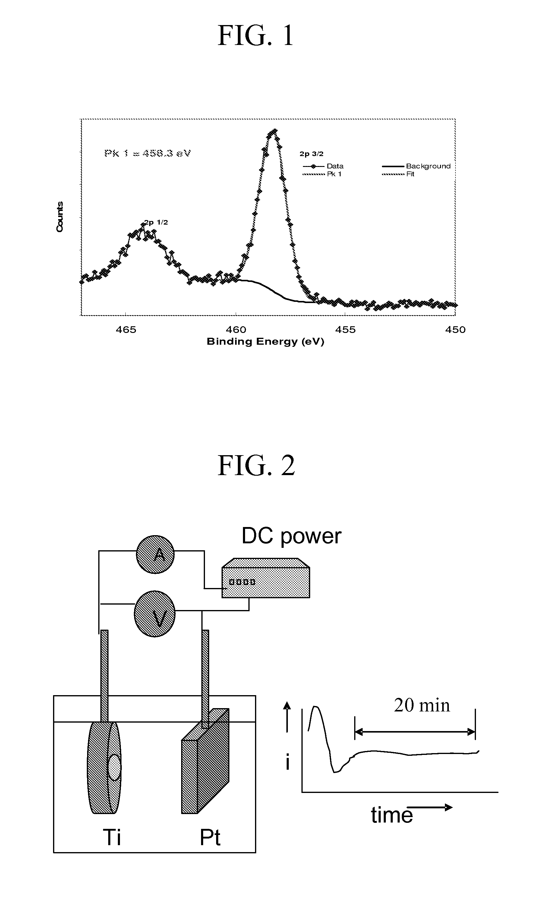
[0136]Step 3: A direct current (DC) power source, which can supply 40 V of potential and support 20 mA / cm2 current density, was connected to the Ti material and a platinum foil (Pt rod / mesh) having an equal or larger area of the Ti surface. The...

example 2

Production of anodized Titanium templates

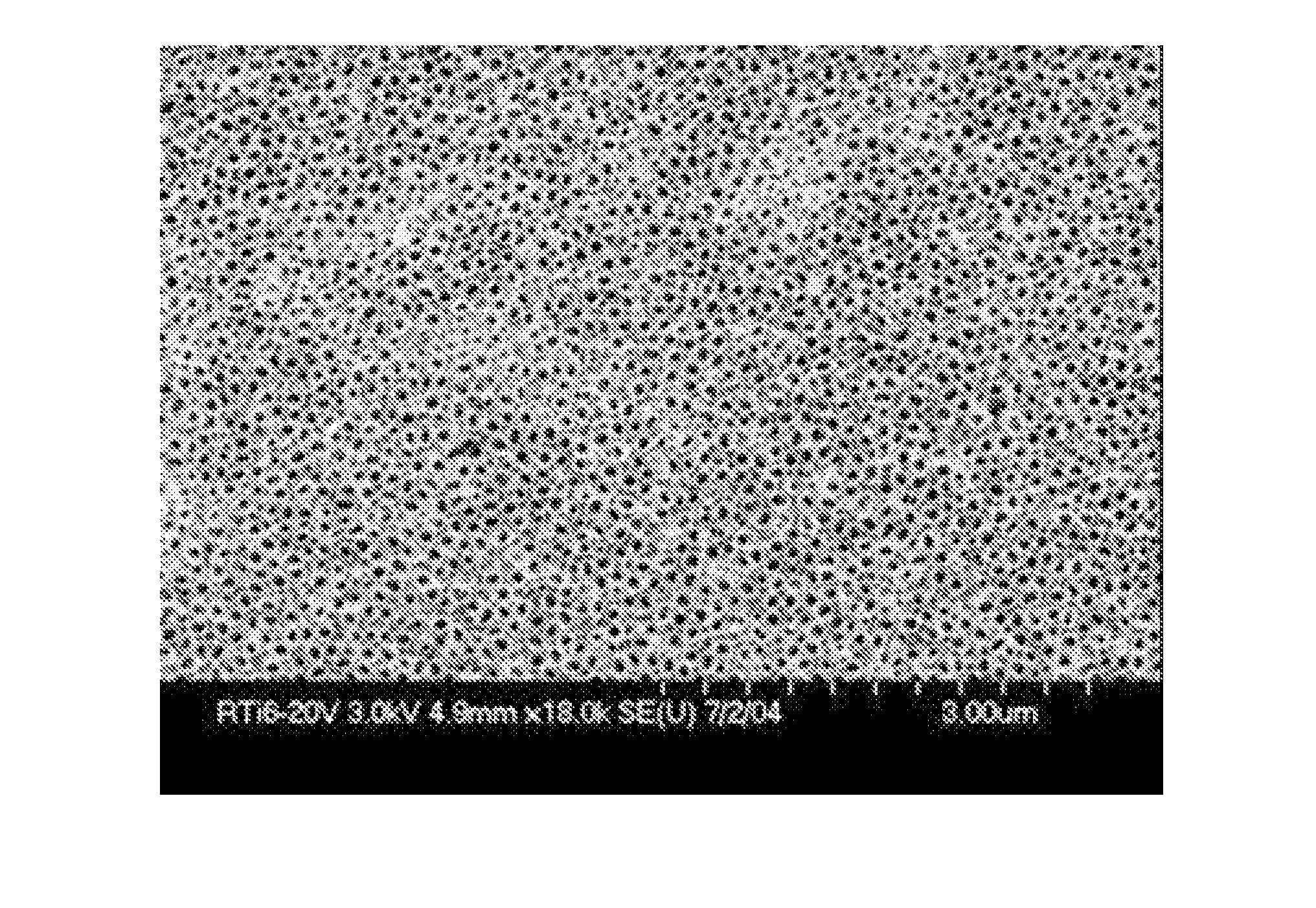
[0141]Titanium discs of diameter 16 mm and thickness 0.2 mm (0.2 mm thick, ESPI-metals, Ashland, Oreg., USA) were cleaned by sonication in acetone, isopropanol and methanol respectively and then rinsed in deionized water. The dried specimens were placed in a Teflon holder (from Applied Princeton Research, Oak Ridge, Tenn.) exposing only 0.7 cm2 of area to the electrolyte for anodization. The solution of 0.5 M H3PO4+0.14 M NaF was used for anodization, conducted at room temperature under a voltage of 20 V for 45 minutes with constant mechanical stirring. The morphologies of the resulting nano-porous titanium oxide were studied using a Hitachi S-4700 field emission scanning electron microscope (FESEM) and Shimadzu UV-VIS photospectrometer.

example 3

Anodization of Titanium in Ethylene Glycol / Glycerol Organic Solvents

[0142]First, anodized titanium templates were prepared. Titanium discs having 16 mm diameters and a thickness of 0.2 mm (0.2 mm thick, ESPI-metals, Ashland, Oreg., USA) were cleaned by sonicating in acetone, isopropanol, and methanol respectively, and then rinsed in deionized water. The dried specimens were then placed in a Teflon holder (from Applied Princeton Research, Oak Ridge, Tenn.) exposing only 1 cm2 of area to the electrolyte for anodization.

[0143]Anodization was done in two types of organic solvents. The first was glycerol based and other was ethylene glycol based. The following combination of electrolytes were used:

[0144](a) 0.5 wt.% NH4F & 8.75 wt.% Ethylene Glycol in Glycerol.

[0145](b) 0.5 wt.% NH4F & 27.5 wt.% Ethylene Glycol in Glycerol.

[0146](c) 0.4 wt.% NH4F in Ethylene Glycol.

[0147]The anodization was done by ramping the potential to 20V at a rate of 1V / s after which the potential was kept constant...


PUM

PropertyMeasurementUnit
pore diameteraaaaaaaaaa
band gapaaaaaaaaaa
thicknessaaaaaaaaaa

Abstract

The invention relates to a method of making a nanotubular titania substrate having a titanium dioxide surface comprised of a plurality of vertically oriented titanium dioxide nanotubes containing oxygen vacancies. The method generally comprises the steps of anodizing a titanium metal substrate in an acidified fluoride electrolyte under conditions sufficient to form a titanium oxide surface comprised of self-ordered titanium oxide nanotubes, dispersing gold nanoparticles onto the titanium oxide surface, annealing the titanium oxide surface with the gold nanoparticles thereon in a non-oxidizing atmosphere, and depositing carbon onto the annealed titanium oxide surface. The invention also relates to a hybrid gold / carbon electrode formed by the method. The invention further relates to a photo-electrolysis method for generating H2 comprising the step of irradiating a photo-anode and a photo-cathode with light under conditions suitable to generate H2, wherein the photo-anode is a nanotubular titania substrate having gold and carbon deposits.

Description

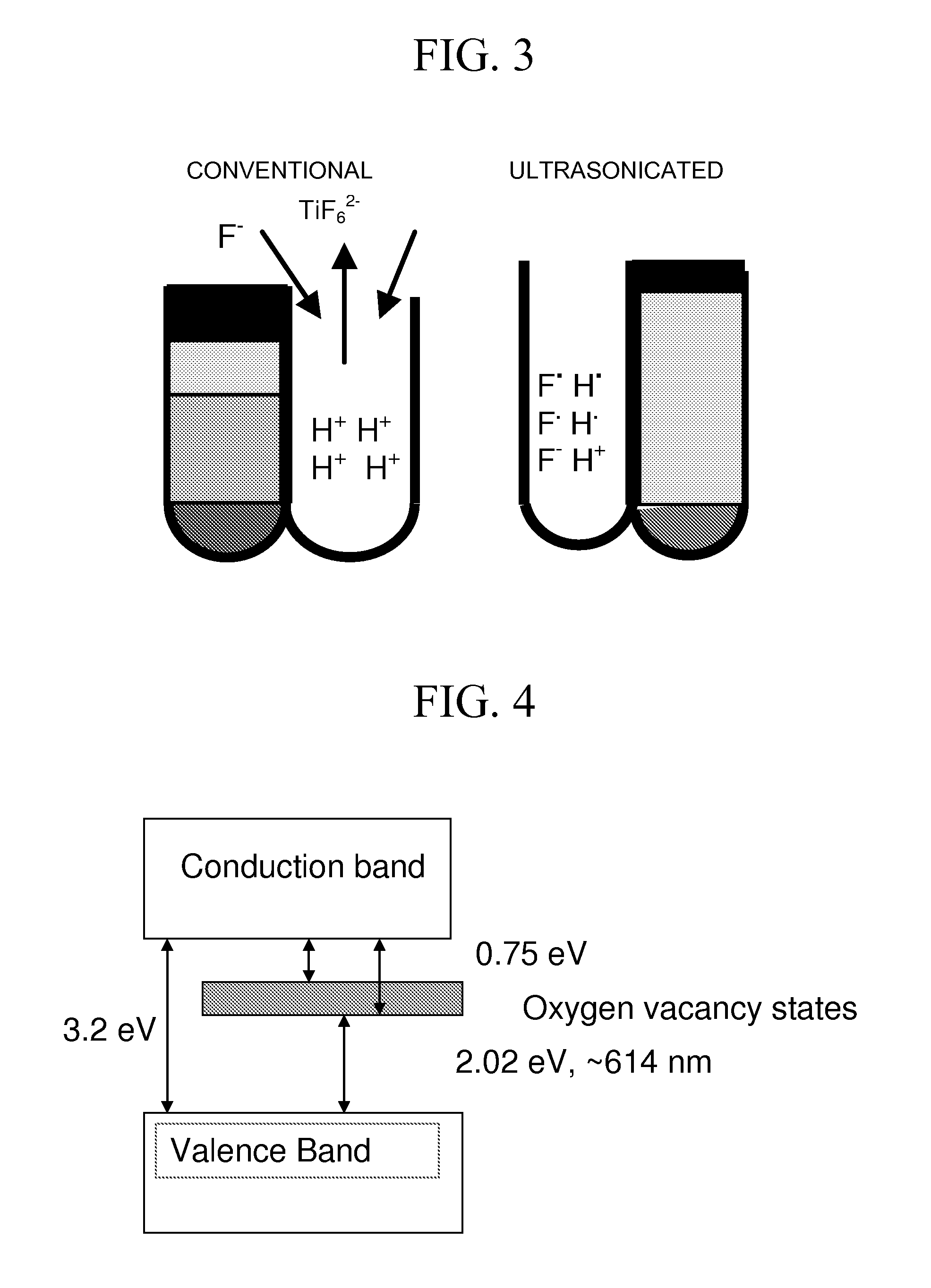
FIELD OF THE INVENTION[0001]This invention relates to hydrogen generation by photo-electrolysis of water with solar light using band gap engineered nano-tubular titanium dioxide photo-anodes. The titanium dioxide nanotubes are formed by anodization of a titania substrate in an acidified fluoride electrolyte, which may be conducted in the presence of an ultrasonic field or mixed by conventional mixing. The electronic band-gap of the titanium dioxide nanotubes is engineered by annealing in a non-oxidizing atmosphere yielding oxygen vacancies and optionally doping various elements such as carbon, nitrogen, phosphorous, sulfur, fluorine, selenium, etc. Reducing the band gap results in absorption of a larger spectrum of solar light, including the visible region, and therefore generates increased photocurrent leading to higher rate of hydrogen generation. In addition, the invention relates to a method of making a hybrid Au / C electrode, and the resulting Au / C electrode, including the steps...

Claims


Application Information

Patent Timeline
Patent Type & Authority Applications(United States)
IPC IPC(8): C25B1/02C23C28/00C25B11/04B01J35/00B82Y20/00B82Y30/00B82Y40/00
CPCB82Y30/00C30B29/16C30B29/602C25B1/003Y02E60/364Y02E60/368H01G9/2031Y02E60/36Y02P20/133C25B1/55
Inventor MISRA, MANORANJANRAJA, KRISHNAN SELVAMOHAPATRA, SUSANTA KUMARMAHAJAN, VISHAL K.
Owner BOARD OF RGT NEVADA SYST OF HIGHER EDUCATION ON BEHALF OF THE UNIV OF NEVADA RENO
Learn More