Microfluidic apparatus and method for DNA extraction, amplification and analysis

a microfluidic and sample technology, applied in the field of microfluidic sample processing devices, methods and systems, can solve the problems of difficult to make a quick shortlist of suspects, use of dna, and potentially inefficient methods of manipulating microlitres of fluid, and achieve the effect of enhancing stability and manufacturing inexpensiv

Inactive Publication Date: 2011-10-06
UNIVERSITY OF HULL
View PDF2 Cites 41 Cited by
  • Summary
  • Abstract
  • Description
  • Claims
  • Application Information

AI Technical Summary

Benefits of technology

[0096]The microfluidic device (300) of the present invention is specifically designed to make its manufacture inexpensive by keeping all the hardware requirements external to the microfluidic device. This allows for the microfluidic device to remain economical and thus ideal for single use analysis which is of course particularly advantageous in the field of forensics or crime scene investigation where the used microfluidic device may be required to form the basis of evidence.
[0097]In the microfluidic device (300) of the present invention, the use of gel filled channels or capillaries to support the process reagents and sample DNA has been found to provide enhanced stability with respect to electro-kinetic control of the sample DNA when compared to solution based (prior art) methodology even when bubbles are present in the system. The gel may be in the form of a matrix but, in whatever form it is present, it should be capable of fixing the different process reagents with precision localisation in the microfluidic device over prolonged periods.

Problems solved by technology

It is therefore difficult to make a quick shortlist of, for example crime suspects, using DNA soon after a crime has occurred.
However in some cases integration has proved difficult to implement due to the high degree of complexity associated with successfully transporting a discrete volume of sample from one area of the device to another without the requirement to couple the device to auxiliary equipment such as pumps.
State of the art microfluidic devices or systems in which they are utilised usually all require external hydrodynamic pumping, with the exception of electrophoretic separation, which is potentially a very inefficient method of manipulating microlitres of fluid as it requires excessive dead volumes.
Furthermore, the prior art devices generally comprise solution based technology and thus it is difficult to prepare and store reagents within a microfluidic device in a manner that will offer stable electro-kinetic control of a sample especially if, for example, air bubbles enter the system or a solution dries.
In particular, practical devices that combine on a single chip modules for DNA extraction and purification from tissue, DNA amplification, sample separation and detection with a practical transport mechanism such that the steps may be performed in successive manner by components in microfluidic communication have proved difficult to fabricate and operate effectively.
Effective and consistent localisation of the different reagents, effective provision of an interface for receiving a real world lysed tissue sample, and an efficient transport mechanism to transport the extracted sample consistently through the chip has particular difficulties.
One of the main issues associated with integration of extraction, amplification and separation and detection within a single device is that integration compromises the known operating conditions for the individual processes.
Re-optimisation of the operating conditions is difficult to achieve as the system must operate as a standalone complex process in which the interaction between the individual processes are harmonised.
For these reasons and others, effective microfluidic devices that perform extraction and purification, amplification, sample separation and detection on a single chip have proved elusive.

Method used


Image

  • Microfluidic apparatus and method for DNA extraction, amplification and analysis
  • Microfluidic apparatus and method for DNA extraction, amplification and analysis
  • Microfluidic apparatus and method for DNA extraction, amplification and analysis

Examples


example 2

[0132]Preparation of PCR Gel

[0133]The PCR gel was prepared by dissolving low melting point agarose gel in DNA / RNA free distilled water and heating to 75° C. for 10 minutes. Once the gel was formed and whilst still in molten form the PCR reagents were added (2 μl of 10× NH4 buffer, 2 μl of BSA, 2 μl of forward primer, 2 μl of reverse primer, 1 μl of dNTPs, 0.4 μl of MgCl and 0.4 μl of Tag polymerase) and mixed, on cooling the gel retained the reagents. Electrodes B and D were secured into place and an electric potential of 100 Vcm−1 applied for 5 min, the experiment was performed on an ice block to maintain the integrity of the PCR reagents. Once the electro-kinetic movement was complete, the PCR gel was removed from the channel by pressure injection and collected. The resulting solution was then amplified in a thermal cycler, separated by slab gel electrophoresis and observed via the UV transilluminator.

[0134]The concentration of the gel and reagents was investigated to determine th...

example 3

[0140]Development of Reagent Gel

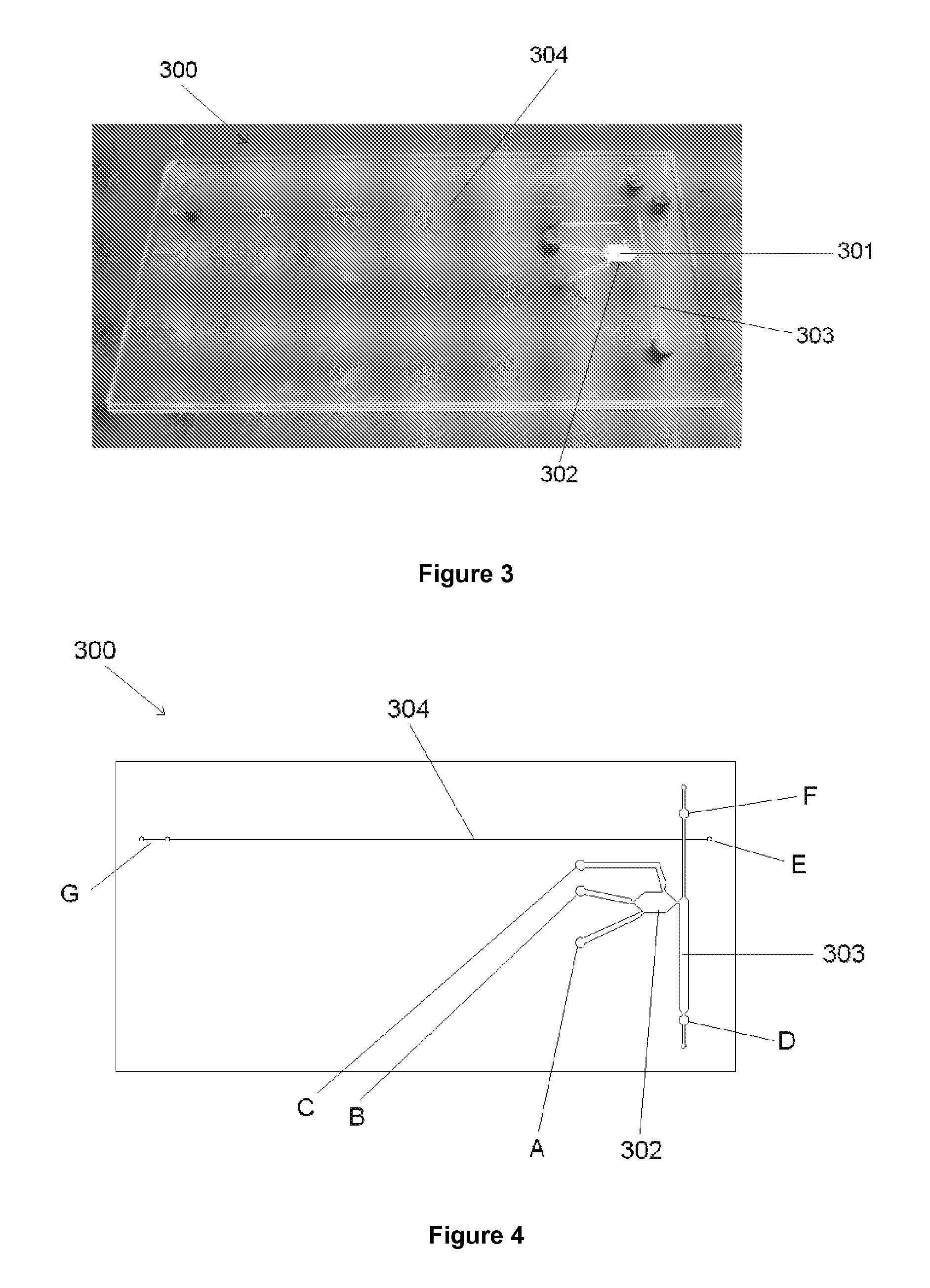
[0141]After the application of the electrical potential, the solution accumulated at each electrode was collected and the DNA quantified 65% of DNA recovered was found at the negative electrode whilst 22% was recovered from the positive electrode (at inlet port F of FIG. 4). This was likely due to a small amount of electrophoretic movement occuring when the DNA was introduced at the same port. The remaining DNA-(13%) was detected in the ethanol wash. These results support the claim that DNA can be succesfully extracted from the monolith by electro-osmotic flow in the concentration required for PCR amplification.

[0142]The DNA extracted from the monolith by electro-osmotic pumping was of sufficient quantity and quality for PCR amplification to be carried out. The results also established the stability of the reagents in gel form even when a relatively high electric field was used.

[0143]A series of agarose gel concentrations were then investigated (10%, ...

example 4

[0146]Preparation of Reagent Gel

[0147]A microfluidic device (300) as shown in for example FIG. 3 or 4 was cleaned and prepared by flushing through with 1M hydrochloric acid followed by 1M sodium hydroxide and deionised water before drying. The PEO gel was loaded into the separation channel (304) of the microfluidic device (300) by pressure injection into port G.

[0148]Agarose gel was then prepared by dissolving 0.0029 g of low melting point agarose in 100 μl of DNA / RNA free water, creating a gel concentration of 2.94%. The solution was then heated in a water bath at 75° C. for 10 min to allow the gel to form. While the gel was still in liquid form, 10.2 μl of the gel was added to 9.8 μl of the sample, the visualisation agent (in this case fluorescently labelled primers) was added and mixed. The final gel solution which had a concentration of 1.5%, was injected into the microfluidic device warm by pressure injection into port E in order to ensure equal filling of sample matrix into bo...


PUM

PropertyMeasurementUnit
sizesaaaaaaaaaa
sizesaaaaaaaaaa
v/vaaaaaaaaaa

Abstract

An integrated gel based microfluidic sample processing device, suitable for forensic investigations at the scene of a crime, including a substrate having a plurality of micro-channels to form at least a DNA extraction chamber in fluidic cooperation with an amplification chamber which in turn is in fluidic cooperation with a separation and detection channel. The micro-channels containing a DNA extraction material and gel based reaction reagents necessary for processing the sample. The device further having electrical contacts for coupling to an external power source and capable of inducing electro-kinetic manipulation of the gel based reagents and DNA extracted from the sample throughout the device.

Description

FIELD OF INVENTION [0001]The present invention relates to a microfluidic sample processing device, methods and system. More particularly, the present invention relates to a microfluidic sample processing device with micro-channels having gel supported samples and reagents, and a fully integrated, portable DNA analyser using same.[0002]State of the art microfluidic devices, also sometimes known as “Lab-on-chip” or “micro-total analysis systems” generally comprise a substrate and microstructures such as micro-channels and ports. The use of such microfluidic devices allows the use of dedicated micro-channels which feature multiple layers of materials such as silicon, glass and polymer thus allowing miniaturisation of normal sized equipment such that it can be readily portable.[0003]Compared to devices of the same type in normal size, such microfluidic devices have various advantages including the fact that only very small amounts of samples and reagents are required, the analysis time ...

Claims


Application Information

Patent Timeline
Patent Type & Authority Applications(United States)
IPC IPC(8): C12Q1/68C12M1/40
CPCB01L3/50273B01L3/502761G01N27/4473B01L7/52B01L2200/0631B01L2200/10B01L2300/0627B01L2300/069B01L2300/0816B01L2300/087B01L2300/1866B01L2400/0415B01L2400/0421C12N15/1003C12Q1/6858C12Q2565/629
Inventor HASWELL, STEPHEN JOHN
Owner UNIVERSITY OF HULL
Why Eureka
Try Eureka