High density capacitor

a capacitor and high density technology, applied in the field of high density capacitors, can solve the problems of not being suitable for high frequency decoupling, not being suitable for capacitors, etc., and achieve the effects of reducing or eliminating discrete voltage steps, large capacitance density, and increasing the capacitance density of integrated devices

Active Publication Date: 2011-12-01
NXP BV
View PDF14 Cites 11 Cited by
  • Summary
  • Abstract
  • Description
  • Claims
  • Application Information

AI Technical Summary

Benefits of technology

[0017]Accordingly, the Li intercalating material is preferably non-crystalline and / or amorphous, in use, since the use of such material reduces or eliminates the discrete voltage steps.
[0018]The use of non-crystalline materials also allows lower temperature processing to be performed, since forming good crystalline layers of Li intercalating material usually requires annealing (temperatures typically above 500° C.). Thus, the thermal budget of the proposed solid state electrochemical capacitor is relatively low, easing integration. Hence, it is possible to deposit such a structure on top of a CMOS device. CMOS processes generally require temperatures after formation of the CMOS devices not to exceed 400° C. or 450° C. to avoid damage to the underlying CMOS layers. This is achievable upon using amorphous materials.
[0019]The full solid state electrochemical capacitor increases the capacitance density of the integrated devices compared with dielectric based capacitors. A full solid state device may withstand high-temperatures during manufacturing, it can be processed with standard lithographic and semiconductor proven technologies, and it can be deposited on top of CMOS. The use of a solid electrolyte ensures that the electrolyte won't leak away which makes it an inherently safer product, and that the electrolyte material and interfaces won't degrade as quickly as a liquid electrolyte would do.
[0020]An extremely large capacitance density can be achieved by the all-solid-state electrochemical capacitor based upon the reversible exchange of lithium ions between two electrodes (anode and cathode), which are separated by a solid-state electrolyte, that allows for Li-ion diffusion-migration and prevents electron transport.
[0021]In addition, diffusion barrier layers may be provided to prevent the diffusion of lithium species from the electrodes into the substrate. These barrier layers (possibly combined with a current collector) should allow for (external) electron transport from anode (negative electrode) towards cathode (positive electrode) during discharge (and vice versa during charge).
[0022]The capacitance is determined by the electrodes and so the thickness of the electrolyte can be adjusted. In embodiments, the thickness of the amorphous solid state electrolyte is 0.5 μm to 10 μm. Smaller thicknesses, for example 0.5 μm to 1 μm improve the high frequency performance. Larger thicknesses, for example 5 μm to 10 μm, improve the resistance of the device to electrostatic discharge.

Problems solved by technology

Such lithium ion batteries are however not suited for high frequency decoupling because the discharge / charge rate is relatively small compared to standard parallel plate capacitors.
Such fixed voltage outputs as a function of charge are of course very useful in a battery, but are not suitable for a capacitor.

Method used


Image

  • High density capacitor
  • High density capacitor
  • High density capacitor

Examples


Embodiment Construction

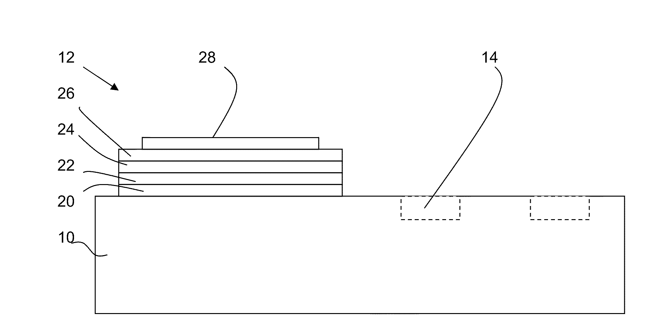
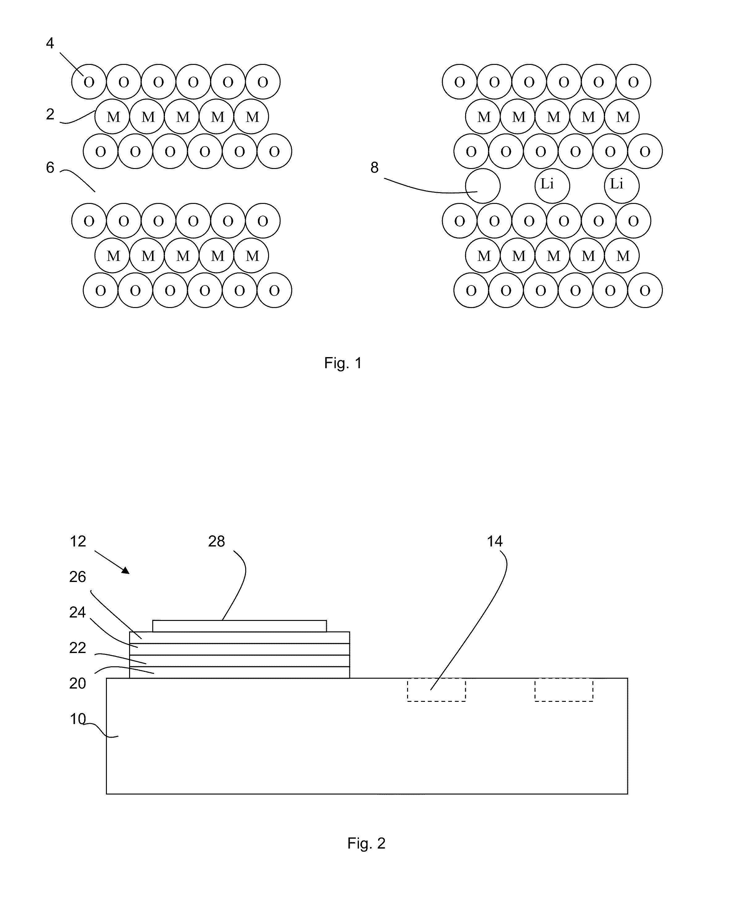
[0031]FIG. 2 shows a first embodiment of an electrochemical capacitor arrangement according to the invention.

[0032]A semiconductor substrate 10 has an electrochemical capacitor 12 formed on the same substrate as semiconductor devices 14. Note that the electrochemical capacitor also works stand-alone on other substrates 10 without semiconductor devices.

[0033]The electrochemical capacitor comprises a diffusion barrier layer 20, which may also function as an adhesion layer and / or a protection layer or even a current collector layer to avoid high Ohmic current paths. In the example shown, this diffusion barrier layer 20 is provided on a layer of silicon dioxide (not shown) on the substrate surface but in alternative embodiments the diffusion barrier layer 20 may be formed on the substrate.

[0034]Suitable materials for the diffusion barrier layer include titanium nitride (TiN), titanium oxide (TiO2), aluminium oxide (Al2O3), tantalum oxide (TaOx) or tantalum nitride (TaN).

[0035]A lower el...


PUM

PropertyMeasurementUnit
thicknessaaaaaaaaaa
thicknessaaaaaaaaaa
temperatureaaaaaaaaaa

Abstract

A high density capacitor 12, a method of manufacturing it, and applications of it are described. The capacitor 12 is an electrochemical capacitor using a metal ion accepting cathode 22 and a metal ion accepting anode 26 and a amorphous solid electrolyte 24 between. The cathode and anode may be of amorphous lithium ion intercalating material such as suitable transition metal oxides with multiple oxidation states.

Description

[0001]This application claims the priority under 35 U.S.C. §119 of European patent application no. 10164669.3, filed on Jun. 1, 2010, the contents of which are incorporated by reference herein.[0002]The invention relates to a high density capacitor, a method of manufacturing it, and applications of it.BACKGROUND OF THE INVENTION[0003]A general trend is the miniaturization of components. In terms of capacitors, new technologies have been developed to integrate thin-film capacitors with high capacitance densities on silicon chips. Two main technology routes are followed: trench capacitors or complex oxide capacitors such as ferroelectric capacitors. Both capacitor types are suited for radio frequency (RF) decoupling. But the capacitors are still not small enough to integrate μF capacitor values on a reasonably small area.[0004]Conventional integrated capacitors store the electrical energy as charge on two parallel plates placed sufficiently close together. Using the parallel plate cap...

Claims


Application Information

Patent Timeline
Patent Type & Authority Applications(United States)
IPC IPC(8): H01G9/04H01G7/00
CPCH01G9/042Y10T29/43H01M10/0525H01G9/28H01G11/02H01G11/06H01G11/46H01G11/50H01G11/56Y02E60/10Y02E60/13
Inventor BESLING, WIMREIMANN, KLAUS
Owner NXP BV
Why Eureka
Try Eureka