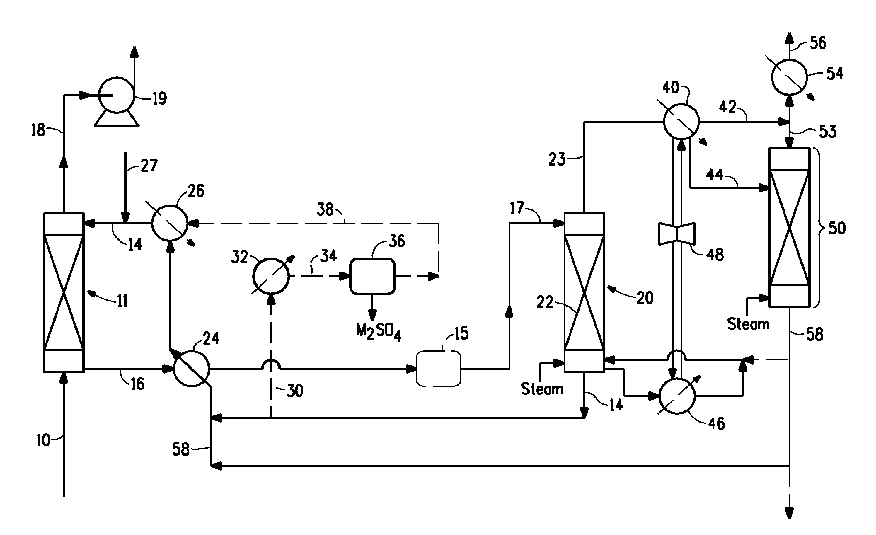
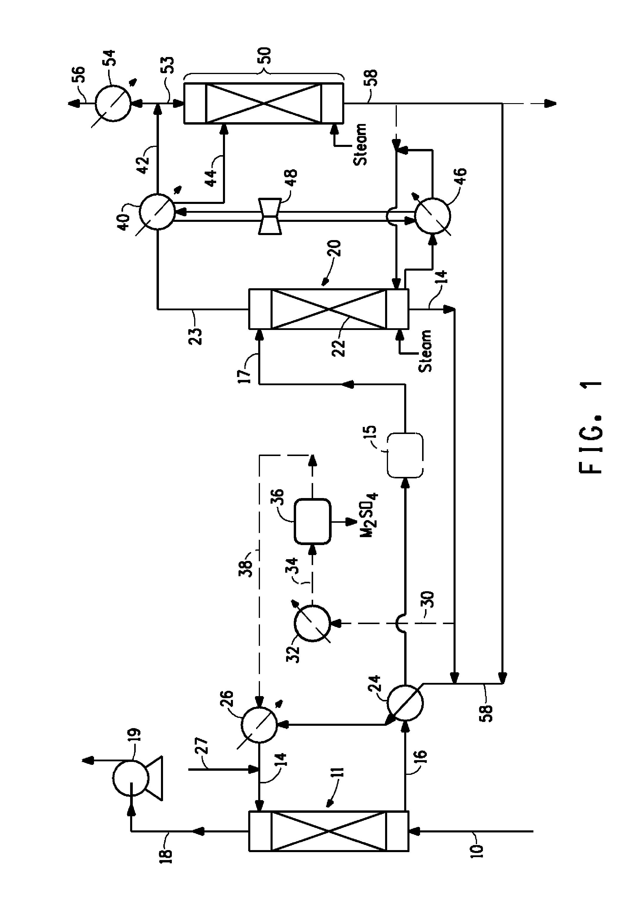
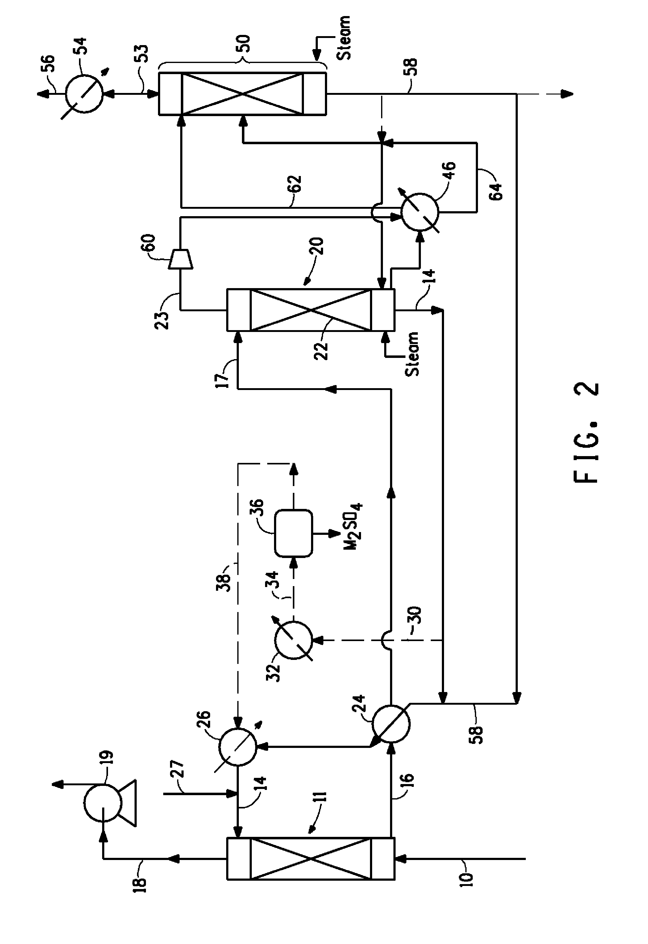
Regenerative recovery of sulfur dioxide from effluent gases

a sulfur dioxide and effluent gas technology, applied in the direction of bulk chemical production, separation processes, human health protection, etc., can solve the problems of increased sulfur dioxide emissions, increased regulatory pressures to reduce sulfur dioxide emissions, and variable costs due to lime consumption. , to achieve the effect of improving energy efficiency

Active Publication Date: 2012-05-03
MECS
View PDF14 Cites 48 Cited by
  • Summary
  • Abstract
  • Description
  • Claims
  • Application Information

AI Technical Summary

Benefits of technology

[0014]In accordance with the present invention, an improved process for the selective removal of contaminants from effluent gases has been devised. In some embodiments of the present invention sulfur dioxide is selectively removed and recovered from effluent gases in a sulfur dioxide absorption/desorption process that utilizes a buffered aqueous absorption solution comprising certain weak inorganic or organic acids or salts thereof, preferably certain polyprotic carboxylic acids or salts thereof, to selectively absorb sulfur dioxide from the effluent gas. The present inventi

Problems solved by technology

The sulfur dioxide emitted contributes to a wide range of environmental and health problems.
As the emerging economies expand, their demands for energy rapidly increase and as lower sulfur content carbon fuels are depleted, more and more oil and coal reserves having increasingly higher levels of sulfur will be utilized leading to increased sulfur dioxide emissions.
There are also increasing regulatory pressures to reduce sulfur dioxide emissions around the world.
Wet scrubbers and similarly dry scrubbers require capital investment, variable costs due to lime consumption and solids disposal, and consume energy and utilities to operate such sulfur dioxide removal systems.
However, these gas streams frequently have relatively low sulfur dioxide concentration and high concentration of water vapor.
Where sulfur dioxide concentration in the gas fed to a sulfuric acid plant is less than about 4 to 5 percent by volume, problems may arise with respect to both water balance and energy balance in the acid plant.
As generated, effluent gases from metallurgical processes and flue gases from the combustion of sulfurous fuels often have a water vapor content well above the 1.08 ratio, which cannot be sufficiently reduced by cooling the gas without significant capital and energy expenditures.
Moreover, if the sulfur dioxide gas strength of the effluent gas is below about 4 to 5 percent by volume, it may not be sufficient for autothermal operation of the catalytic converter.
That is, the heat of conversion of sulfur dioxide to sulfur trioxide may not be grea

Method used


Image

  • Regenerative recovery of sulfur dioxide from effluent gases
  • Regenerative recovery of sulfur dioxide from effluent gases
  • Regenerative recovery of sulfur dioxide from effluent gases

Examples


example 1

Batch Absorber Experiments

[0076]The following experiments were conducted in a batch absorber wherein a sulfur dioxide-containing gas was fed via a sparger below the liquid level in a vessel containing an aqueous absorption solution comprising various polyprotic carboxylic acid salts and the composition of the exhaust gas was monitored. A schematic of the experimental apparatus is shown in FIG. 3.

[0077]The sulfur dioxide-containing inlet gas 101 to be treated comprised nitrogen saturated with water vapor and a controlled concentration of sulfur dioxide. Temperatures (T) and pressure (P) were monitored during the experiment and gas samples (S) were taken at different times during the experiment. T1 and P1 are temperature and pressure sensors of inlet gas 101. S1 is a sampling point for inlet gas 101. T2 is a temperature sensor of the liquid in the vessel. T3 is a temperature sensor of exhaust gas 102.

[0078]In these experiments and other experiments reported in the Examples below, the ...

example 2

Absorber Column Experiments

[0083]In the following experiments a gas comprising nitrogen and oxygen saturated with water and containing sulfur dioxide was contacted with an absorption solution in a counter current absorber column.

[0084]A schematic of the experimental apparatus is shown in FIG. 5. Fresh absorption solution 201 was introduced to absorber column 202. Counter current absorber column 202 was equipped with 1.92 meters (75.5 inches) of structured packing and was operated at a temperature of 33.4° C. and at atmospheric pressure (1 atm=101.3 kPa). Inlet gas 203 was introduced to the bottom of absorber column 202. Exhaust gas 204 was removed from the top of absorber column 202. The compositions of inlet gas 203 and exhaust gas 204 were monitored and are reported in Table 3. Fresh absorption solution 201 comprised an aqueous solution of sodium malate and ascorbic acid as an oxidation inhibitor. In the experiments, gas samples could be taken along absorber column 202 via various...

example 3

Stripper Experiments

[0086]In the following experiments a sulfur dioxide-enriched absorption solution was stripped to remove sulfur dioxide by heating the solution.

[0087]A schematic of the experimental apparatus is shown in FIG. 6. Feed reservoir 301 contains sulfur dioxide-enriched absorption solution 302 collected during the absorption experiments. Absorption solution 302 comprised an aqueous solution containing 24% sodium malate and 3.7 weight % sulfur dioxide by weight. Absorption solution 302 was fed as monitored by burette 303 at a rate of 47.2 grams / minute using first positive displacement pump 304 to stripper column 306. Absorption solution 302 was pumped through first pump 304 and preheated in hot bath 305 and fed to stripper column 306 consisting of 35 trays. The top portion 307 of stripper column 306 contained 25 trays (stages) and the bottom portion 308 of stripper column 306 contained 10 trays (stages).

[0088]Stripper column 306 was operated at atmospheric pressure (1 atm...


PUM


Abstract

This invention relates to processes for selective removal of contaminants from effluent gases. A sulfur dioxide absorption/desorption process for selective removal and recovery of sulfur dioxide from effluent gases utilizes a buffered aqueous absorption solution comprising weak inorganic or organic acids or salts thereof, to selectively absorb sulfur dioxide from the effluent gas. Absorbed sulfur dioxide is subsequently stripped to regenerate the absorption solution and produce a sulfur dioxide-enriched gas. A process for simultaneous removal of sulfur dioxide and nitrogen oxides (NOx) from effluent gases and recovery of sulfur dioxide utilizes a buffered aqueous absorption solution including a metal chelate to absorb sulfur dioxide and NOx from the gas and subsequently reducing absorbed NOx to form nitrogen. A process to control sulfate salt contaminant concentration in the absorption solution involves partial crystallization and removal of sulfate salt crystals.

Description

FIELD OF THE INVENTION[0001]This invention relates to processes for the selective removal of contaminants from effluent gases. The present invention is particularly useful in producing a sulfur dioxide-enriched gas from effluent gases relatively weak in sulfur dioxide content.BACKGROUND OF THE INVENTION[0002]Gaseous effluents containing sulfur dioxide are produced by a variety of operations, including roasting or smelting of sulfidic metal ores and concentrates and the combustion of sulfur-containing carbon fuels (e.g., flue gases from coal-fired power plants). Carbon fuels play a significant role in the generation of electricity, providing energy for heating and fuels for transportation. Most carbon fuels contain sulfur that when burned turns into sulfur dioxide. The sulfur dioxide emitted contributes to a wide range of environmental and health problems. As the emerging economies expand, their demands for energy rapidly increase and as lower sulfur content carbon fuels are depleted...

Claims


Application Information

Patent Timeline
IPC IPC(8): B01D53/50B01D53/60C01B17/48
CPCB01D53/1425B01D53/1481B01D53/507B01D2257/80C01B17/0408Y02A50/2349C01B17/96Y02P20/123Y02P20/129Y02P20/57C01B17/60Y02P20/10Y02P20/50B01D53/60B01D53/96B01D2251/304B01D2251/306B01D53/50B01D53/1493B01D53/1418B01D53/002C01B17/56Y02A50/20
Inventor VERA-CASTANEDA, ERNESTO
Owner MECS
Why Eureka
Try Eureka