Method for curing substances by UV radiation, device for carrying out said method and ink cured by UV radiation

a technology of uv radiation and curing method, which is applied in the direction of printing press, ink, printing, etc., can solve the problems of low efficiency factor, high operating temperature, and ink or paint on the substrate, and achieve the effect of avoiding fluorescent lamps, stable operating temperature, and high efficiency factor

Inactive Publication Date: 2012-05-24
MIRCHEV VLADISLAV YURIEVICH
View PDF3 Cites 68 Cited by
  • Summary
  • Abstract
  • Description
  • Claims
  • Application Information

AI Technical Summary

Benefits of technology

[0052]As stated above, the printing ink comprises: photopolymer, photoinitiator and solid insoluble pigment that is resistant to UV radiation, which does not fade under UV radiation exposure, for example, soot for black color. Under UV radiation exposure, the photoinitiator breaks internal links. Substances resulting from the breaking, react chemically with the photopolymer. As a result of this reaction, the polymer (plastic) is formed. The main problem with this is that the pigment retains UV radiation—90% of the radiation is delayed by ⅛ of the upper ink layer, whereby the chemical reaction occurs slowly. A twofold radiation power increase can increase the reaction rate several times. With the proper semiconductor crystal cooling, the current density can be 5-7 times higher than rating value. Therefore, to achieve a radiator high power, an efficient cooling system is needed that allows effectively cooling the crystal with power increasing and preventing both the crystal degradation and the radiation intensity reducing across the LED. The most effective and low-cost cooling system is a water cooling system.
[0057]The structure diagram and method of agent curing by UV radiation is shown in FIG. 1, and the device is shown in FIG. 2. The device contains UV radiation source 1b as rows 2 of UV LEDs that are connected in series with the same spectrum radiation, corresponding to the spectrum area, where the photoinitiators of agents curing have a maximum sensitivity. Rows 2 of UV LEDs are located on the radiator 3, here, a water heat exchanger for effective UV LEDs cooling. Temperature sensor 4 is located directly on the radiator 3 and serves to control the temperature of the UV LEDs. UV radiation source 1 has system 5 to focus optical radiation, formed as a set of lenses, as shown in FIG. 2. Control block 6 is intended to generate UV LEDs control pulses and comprises a controller 7, and a block of power modules 8. The temperature sensor 4 is related to the control input of the control block 6, which is the control input of the controller 7. Series of UV LEDs 2 are fixed directly on the radiator 3, for example, by soldering. The heat from UV LEDs flows to the radiator 3, which is effectively cooled by means of water flow cooling system (not shown in figures). All UV LEDs are located in the same plane on the same surface of the radiator 3. UV LEDs that are used in the device have high power consumption, more than 1 watt per crystal, and they are mounted on the radiator 3 with high density at a minimum distance between housings. The UV LED surface is protected from damage by means of the system 5 of optical focusing of the radiation, which is a lens system for optical power increase per surface unit that are made of materials that pass UV radiation, in one direction.
[0059]The heat exchanger's other side is cooled with liquid. The water cooling system has a small size and allows high-power UV LEDs efficient cooling.
[0065]The power module 8, receiving the control signals from the controller 7, generates the current pulses in the line 2 of UV LEDs of a magnitude and a duty wide that comply with the control signals of the controller 7. When current pulses flow through UV LEDs of lines 2, they produce UV radiation and heat. Heat generated by UV LEDs, should be sent to the radiator 3 with water-cooling, where it is dissipated. UV radiation, passing through the optical system 5 forms a beam, i.e., it comes to a focus. Focused UV radiation should be directed to the substrate coated with UV curable agent. Thus, the described method of agent curing by UV radiation and device for its implementation, first, allows avoiding use of fluorescent lamps, and a higher efficiency factor, stable operating temperature, greater timing budgets, improved environmental friendliness due to ozone elimination, and less power consumption. The field of use of both proposed method of agents curing by UV radiation and device for its implementation is increased. In addition, using only UV LEDs simplifies and reduces the cost of agent curing by UV radiation. The use of UV LEDs with the same range of UV radiation provides its full compliance with the wavelength where the photoinitiator has a maximum sensitivity that increases the efficiency of agents curing.
[0066]The control of the intensity of the LEDs radiation is based on indications of UV LEDs current sensor, as well as feedback and temperature stabilization, allows to reduce the crystal degradation, and increase the radiation intensity of UV LEDs. The effectiveness of the radiation intensity is also increased due to the fact that UV LEDs are located directly on the radiator, rather than on the substrate. The fact that the temperature sensor is located directly on the radiator, rather than on the substrate, also serves to the reduce crystal degradation. Since all UV LEDs are connected in series, and all UV LEDs have the radiation with the same wavelength, it is not necessary to increase the current in LEDs, which reduces the cost of UV agent curing. In addition, in this case, the stability of the current through the UV LEDs is increased, and hence the stability of LEDs radiation intensity increases.
[0068]Consequently, the proposed invention provides a device for agent curing by UV radiation that increases the efficiency of the LEDs control system and LED cooling system due to reduction of crystal degradation of LEDs, and provides the device simplification, reducing its mass-dimensional parameters, and providing an ability providing to mount it, for example, on printer moving parts, as well as cost reduction and improvement of UV agents curing manufacturability, environmental friendliness increasing, power consumption decreasing, extending the operating life by avoiding use of fluorescent lamps and use of LEDs with the same radiation spectrum, as well as due to creation of anaerobic areas. As a result, the proposed invention can be used in piezo-ink-jet full-color printers with different types of print heads, to get full-color large-format image on surfaces of different materials, such as flexible and sheet polymers, glass, metal, ceramics, wood, etc. At the same time, the invention provides a high curing rate of UV curable material in a narrow range of UV radiation.

Problems solved by technology
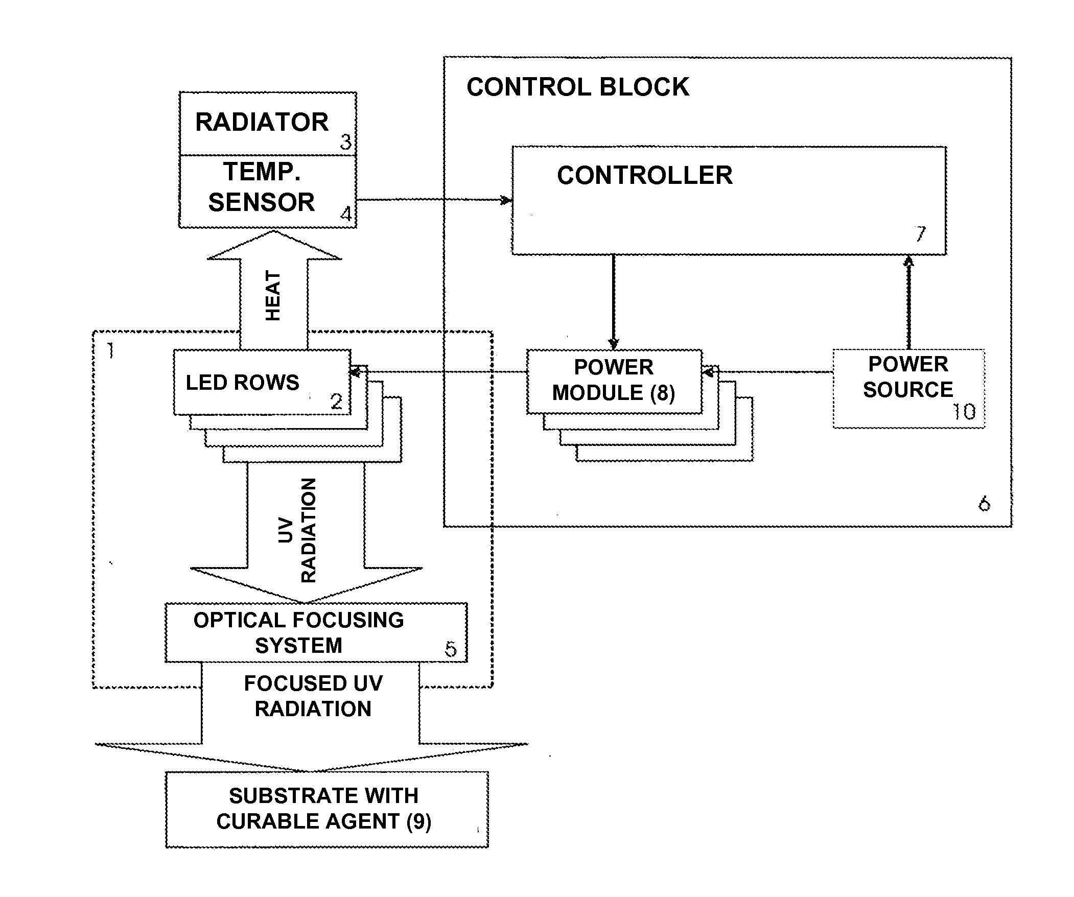
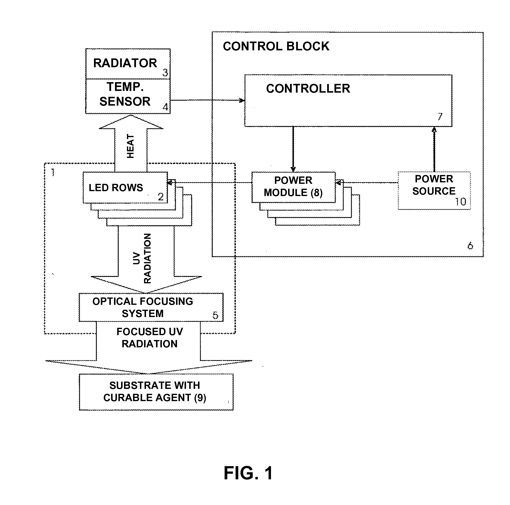
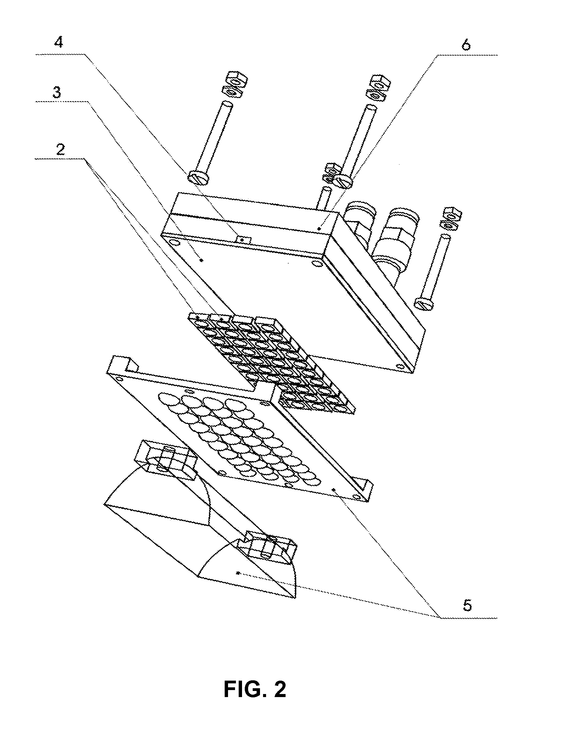
To ensure high printing quality, the spreading of ink or paint on the substrate is absolutely unacceptable, and therefore, special methods of rapid ink curing, upon printing, devices for fast ink curing and special inks, are needed.
The known method of substance curing by UV radiation and device for its implementation use of fluorescent lamps, and hence they have all the detriments that are related to fluorescent lamps, such as low efficiency factor, high operating temperature, short life, low environmental friendliness due to ozone release, a large power consumption, restraining the area of their application.
In particular, they cannot be used in piezo-ink-jet full-color printers with various types of print heads to get full-color image on surfaces of various materials such as flexible and sheet polymers, glass, metal, ceramics, wood, etc., at the same time providing a high cure rate of a sufficiently thick layer of UV curable substance.
Use, at the same time, of both fluorescent lamps and UV LEDs also complicates the process and increases the cost of agent curing by UV radiation.
Since the known photoinitiators have maximum sensitivity in the wavelengths range not more than 365 nm, the use of LEDs having radiation with longer wavelength is not effective.
The use of UV radiation for agent curing with a broad spectrum of radiation is not effective because it leads to decrease of UV radiation intensity in that part of the spectrum, where the photoinitiators included in the composition of the cured substance have a maximum sensitivity.
Reducing the number of LEDs, to which a photoinitiator reacts and implementing the LEDs with longer wavelength, e.g., 400 nm, results in effective radiation power decrease at the wavelength for which the photoinitiator is designed.
Control of LEDs radiation intensity by sensor readings of radiation intensity, as well as with use of feedback and stabilization of the temperature, is not effective.
Such radiation intensity control system is not effective, because it does not allow preventing the crystal degradation of LEDs, since they do not locate on the radiator, once the substrate that is mounted on the radiator.
The need for such selection leads to the increase of the cost of the process of UV substance curing.
In addition, after LEDs heat up their internal resistance and, consequently, the current through the LEDs changes, resulting in the different LEDs radiation intensity.
Besides the use of different types of LEDs radiating light with different wavelength and having different characteristics complicates the LEDs control system.
The above-mentioned deficiencies, lead to limitation in both field of use of the method of agent curing with UV radiation and device for its implementation, due to inability to use, for example, in piezo-ink-jet full-color printers with different types of print heads to get full-color image on surfaces of various materials such as flexible and sheet polymers, glass, metal, ceramics, wood, etc., due to low UV radiation intensity in the part of the spectrum, where the photoinitiators have a maximum sensitivity, and they have inability to provide high speed of curing a sufficiently thick layer of UV curing agents.
The inks are designed for curing by a wide range of UV radiation, and using a narrow range often will not cure them.
However, in printers, it is not possible to use plasma discharges.
The main deficiency of these compositions is their high viscosity, which does not provide adequate print quality with piezo-ink-jet printers.
Similar ink with such rheological properties, primarily increased viscosity, does not allow getting high-quality printing on large- formatting full-color piezo-ink-jet printers, i.e., they have a limited field of use.
Besides photoinitiators used in the above-described ink do not provide the maximum sensitivity in spectrum of ultraviolet radiation with 365 nm wavelength that have the most powerful of the UV-LEDs, which are the most effective and economic sources of UV radiation that are used in modem large-format piezo-ink-jet printers currently.

Method used


Image

  • Method for curing substances by UV radiation, device for carrying out said method and ink cured by UV radiation
  • Method for curing substances by UV radiation, device for carrying out said method and ink cured by UV radiation
  • Method for curing substances by UV radiation, device for carrying out said method and ink cured by UV radiation

Examples


example 2

[0082]Preparation of UV Curable Black Ink.

[0083]The laboratory bead mill, with capacity of 1 liter, should be charged by: 1 kg of ceramic beads with the diameter of 0.6-0.8 mm; 75 g of black pigment—Carbon Black 7 (SB250 gas black, produced by Degussa); 350 g of modified difunctional acrylate (ViaJet 100 produced by CYTEC); 75 g of SN13 hyperdispersant and 75 g of SN10S (produced by TATI); 0.225 g of NPAL fotostabilizator (produced by WAKO Q1301), previously dissolved in 4.275 g dipropyleneglycoldiaacrylate.

[0084]Next, grinding and dispersion for 15 h to obtain the homogeneous mass with average particle size less than 0.5 microns comes. Then to the pigment paste should be added the following: 1520 g of modified difunctional acrylate (ViaJet 400 produced by CYTEC); 300 g of monofunctional acrylate (isoboronnileacrilate produced by CYTEC); 300 g of multifunctional acrylate (dipentaerythritolhexaacrylate, produced by Eternal). The mass should be filtered through 3-stage filter with 3-1...

example 3

[0087]Preparation of UV Curable Blue Ink.

[0088]The laboratory bead mill, with capacity of 1 liter, should be charged by: 1 kg of ceramic beads with the diameter of 0.6-0.8 mm; 30 g of blue pigment Phthalocyanine blue 15:3 (Hostapern Blue B2G-D, produced by Clariant); 350 g of modified difunctional acrylate (ViaJet 100. produced by CYTEC); per 3 g of the following hyperdispers ants: CH 13, CH 13B, CH11B, CH-10S (produced by TATI); 0.225 g of NPAL photostabilizator (produced by WAKO Q1301), previously dissolved in 4.275 g of dipropyleneglycoldiaacrylate. Next, grinding and dispersion for 15 h to obtain the homogeneous mass with average particle size less than 0.5 microns comes. Then to the pigment paste should be added: 1853 g of difunctional modified acrylate (ViaJet 400, produced by CYTEC); 300 g of monofunctional acrylate (isoboronnileacrilate, produced by CYTEC); 250 g of multifunctional acrylate (propoxylatepentaerythrinoltetraacrylaye), produced by Eternal. Then the mass should ...

example 4

[0090]Preparation of UV curable red ink. The laboratory bead mill, with capacity of 1 liter, should be charged by: 1 kg of ceramic beads with diameter of 0.6-0.8 mm; 30 g of red pigment, quinacridone red 122 (Hostapern Red E5B, produced by Clariant); 350 g of modified difunctional acrylate (ViaJet 100. produced by CYTEC); per 3 g of the following hyperdispersants: CH 13, CH 13B, CH11B, CH-10S (produced by TATI); 0.225 g NPAL photostabilizator (produced by WAKO Q1301), previously dissolved in 4.275 g of dipropyleneglycoldiaacrylate Next, both grinding and dispersion for 15 h to obtain the homogeneous mass with average particle size less than 0.5 microns. Then, to the pigment paste should be added: 1853 g of difunctional modified acrylate (ViaJet 400. produced by CYTEC); 350 g of monofunctional acrylate (isoboronnileacrilate, produced by CYTEC); 200 g of multifunctional acrylate (industrial monomer EM-6362 with 12-14 functional groups), produced by Eternal. Then the mass should be fil...


PUM

PropertyMeasurementUnit
wavelengthaaaaaaaaaa
wavelengthsaaaaaaaaaa

Abstract

The proposed method of substance curing by radiation, received from the UV LEDs, the device designed to implement this method, and ink cured by radiation from UV LEDs.

Description

[0001]The present application is a U.S. national stage of the PCT / RU2009 / 000151, filed on Oct. 29, 2009, which claims priority to RU 2008115985, filed on Apr. 22, 2008 and RU 2008115986, filed on Apr. 22, 2008, which are incorporated herein by reference in their entirety.TECHNICAL FIELD[0002]The invention is related to full-color large-format printing on substrates of different materials, such as flexible and sheet polymers, glass, metal, ceramic, wood products, etc.BACKGROUND OF THE RELATED ART[0003]Large-format printing, such as digital multicolor ink-jet printing on roll substrates, is one of the most popular methods of production of advertising materials, high-quality reproductions and other pictorial images. It is used to create both the interior objects, such as large-format wall banners, posters, window advertisements, mobile stands and light panels at trade fairs, and exterior (outside / outdoor) objects, such as posters, large format banners, outdoor signs, standers, lightbox...

Claims


Application Information

Patent Timeline
Patent Type & Authority Applications(United States)
IPC IPC(8): C08F2/46
CPCB41M7/0081C09D11/101B41F23/0409B41F23/0453
Inventor MIRCHEV, VLADISLAV YURIEVICH
Owner MIRCHEV VLADISLAV YURIEVICH
Why Eureka
Try Eureka