Microfluidic reactor system

a microfluidic reactor and microfluidic technology, applied in the field of biological assays, can solve the problems of large hybridization chambers, inconvenient or complicated equipment not readily adaptable, and the inability to mix small volumes, etc., and achieve the effect of reducing the incubation time and the mean flow velocity

Active Publication Date: 2012-07-12
PERKINELMER HEALTH SCIENCES INC
View PDF0 Cites 140 Cited by
  • Summary
  • Abstract
  • Description
  • Claims
  • Application Information

AI Technical Summary

Benefits of technology

[0014]Complete enzyme-linked immunosorbent assay (ELISA) systems in a microfluidic device format are provided for detection of a wide spectrum of biomarker molecules. Such devices are generally disposable and low-cost. Bioassays adapted to a robust microfluidics device format include solid phase affinity-capture assays such as those based on antibody/antigen, antigen/antibody, antibody/protein A, glycomer/lectin, and, generally, signal molecule/receptor as target:affinity-capture pairs. Preferred solid phase affinity-capture assay systems for ELISA include antibody/antigen, antigen/antibody, antibody/protein A, streptavidin/avidin, and histidine/NTA target:affinity-capture pairs. Enzyme-linked antibodies, antigens, streptavidin, and histidine-rich proteins are generally available or may be synthesized by techniques well known in the art. Detection systems for immunoaffinity capture and tagging or amplification of target biomarker signals include, for example, enzyme-linked conjugates and chromogenic substrates (immunochromogenic and ELISA-type detection), streptavidin-enzyme conjugates (again with ELISA-type or immunochromogenic detection), antibody-coupled beads, antigen-coupled beads (with immunoprecipitin or agglutination-type detection), protein A-coupled beads, streptavidin-coupled beads, and enzyme- or bead-conjugated protein-histidine-nickel chelates. Beads for tagging can be colored, fluorescent, luminescent, ta

Problems solved by technology

Mixing small volumes, however, is not without unique problems.
However, these methods depend on relatively large sample volumes, large hybridization chambers and inconvenient or complicated equipment not readily adapted to the point of care.
The pressurization of an open vented system containing hazardous sample is a serious disadvantage of the teachings of U.S. Pat. No. 5,718

Method used


Image

  • Microfluidic reactor system
  • Microfluidic reactor system
  • Microfluidic reactor system

Examples


example 1

Preparation and Assembly of a Microfluidic Assay Device

[0217]A microfluidic device for ELISA immunoassay was prepared as follows:

1. Human IgG (0.5 ug in bicarbonate binding buffer pH 9) was deposited onto a plasma-treated test field of a PET sheet. Human IgM was applied as a negative control to a second test field. The proteins were then fixed to the plastic by drying for 5 minutes at 60° C.

2. After fixation, the test fields were blocked for 30 minutes with casein buffer (biotin free) and washed twice with PBST (phosphate buffered saline with 0.1% TWEEN 20).

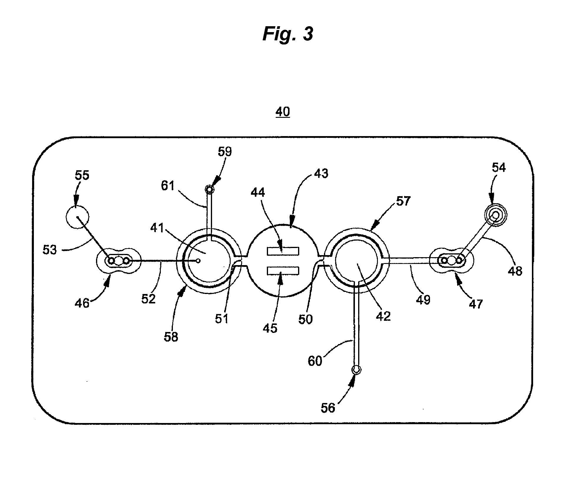
3. After drying, the treated PET sheets were then assembled between adhesive layers in the microfluidic device of FIG. 3 with integrated pneumatic circuitry for pressurizing the bellows pumps and opening and closing sanitary valves.

example 2

Performance of an ELISA Immunoassay in a Microfluidic Device

[0218]A standard assay for ELISA, useful as a benchmark in method development, involves detection of immobilized human IgG on a solid substrate, followed by blocking and detection of the IgG with biotin-labelled anti-human antibody. The biotin in turn is detected with enzyme-labelled streptavidin.

Procedure:

[0219]1. Referring to the microfluidic device prepared as described in Example 1, anti-human IgG biotin (Pierce, 180 uL, 1:10,000 in casein buffer) was added through the sample port, and the device was incubated for 1 min with slow mixing. The test fields were then rinsed with PBST, with slow mixing for 1 min before removing the rinse. A Microflow microfluidics assay instrument (Micronics, Redmond Wash. USA) was used to perform mixing and washing.

2. Detection reagent (Poly SA-HRP) was added with incubation for 1 min with slow mixing. Poly SA-HRP is streptavidin labeled with horseradish peroxidase. The test fields were aga...

example 3

Assembly of a Microfluidic Device for Immunoassay of Antibodies to Capsular Polysaccharides of Streptococcus pyogenes

Assembly of Test Card:

[0221]1. Capsular mucosaccharide antigen purified from Group A Streptococcus pyogenes is immobilized on a N2 plasma activated polyester sheet by co-polymerization with acrylamide monomer. The sheet is previously masked to define the test field area.

2. The plasma treated test field and surrounding areas are then blocked for 30 minutes with casein buffer and washed twice with PBST (phosphate buffered saline with 0.1% TWEEN 20).

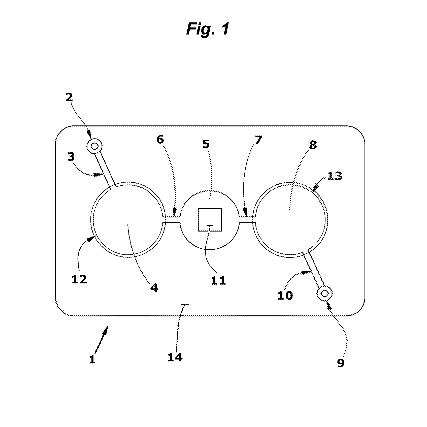
3. After drying, a stack of laminate layers including the antigen-treated polyester sheet are assembled in a microfluidic device generally dimensioned as described in FIG. 9 and assembled with fluidic circuitry per the pattern of FIG. 1.


PUM


Abstract

A compact device for operatively coupling a solid planar substrate, for example a glass slide, to a microfluidic circuit and performing a reaction or reactions on organic matter bound to the face of the planar substrate. Typical reactions include binding, staining and/or labeling reactions. In use, a sealed reaction chamber is formed, the chamber enclosing the organic matter and at least a part of the solid substrate. Headspace in the sealed chamber between the solid substrate is generally of microfluidic dimensions, and diaphragm pump members are used to inject, exchange and/or mix the fluids in the chamber.

Description

CROSS-REFERENCE TO RELATED APPLICATIONS[0001]This application is a Continuation-In-Part of U.S. patent application Ser. No. 12 / 341,637, filed Dec. 22, 2008, now allowed, which is a continuation of International Application No. PCT / US2007 / 014522, filed on Jun. 22, 2007, which claims the benefit under 35 U.S.C. 119(e) of U.S. Provisional Patent Application No. 60 / 816,204, filed Jun. 23, 2006. This application is a Continuation-In-Part of U.S. patent application Ser. No. 13 / 099,187, filed on May 2, 2011, now pending, which is a continuation of U.S. patent application Ser. No. 12 / 685,546, filed on Jan. 11, 2010, now issued as U.S. Pat. No. 7,955,836, which is a divisional of U.S. patent application Ser. No. 11 / 562,611, filed Nov. 22, 2006, now issued as U.S. Pat. No. 7,763,453, which claims the benefit under 35 U.S.C. 119(e) of U.S. Provisional Patent Application No. 60 / 740,697, filed on Nov. 30, 2005. All said patent documents are each incorporated herein by reference in their entireti...

Claims


Application Information

Patent Timeline
IPC IPC(8): B01J8/00
CPCB01F11/0071G01N33/54366B01F13/0059B01L3/502715B01L3/50273B01L3/502738B01L2200/027B01L2200/0689B01L2300/0636B01L2300/069B01L2300/0816B01L2300/0867B01L2300/0887B01L2400/0481B01L2400/0638F04B43/02F04B43/043F04B43/06B01F11/0074B01F31/651B01F31/65B01F33/30
Inventor BATTRELL, C. FREDERICKCLEMMENS, JOHNSPRAGUE, ISAAC
Owner PERKINELMER HEALTH SCIENCES INC
Why Eureka
Try Eureka