Solar receiver and associated energy conversion apparatus

a technology of solar receiver and energy conversion apparatus, which is applied in the direction of solar heat systems, lighting and heating apparatus, pv power plants, etc., can solve the problems of significant diminishing the ability of the system to transfer heat into the working fluid, poor thermal conductivity of the materials system, poor thermal conductivity of the materials, etc., to achieve continuous improvement of absorption properties, maximum temperature gradient, and time-of-day and time-of-year changes of optical absorption properties of the heat transfer fluid

Inactive Publication Date: 2013-12-05
HILLIARD DONALD BENNETT
View PDF6 Cites 38 Cited by
  • Summary
  • Abstract
  • Description
  • Claims
  • Application Information

AI Technical Summary

Benefits of technology

[0018]An according advantage of the present invention is that, utilizing highly non-equilibrium thermal dynamics of the preferred embodiments, normal limitations of black-body thermodynamics limiting prior art receiver tubes can be effectively overcome, and so that, in the present invention, the normal thermodynamic constraints of Kirchoffs Law can be effectively circumvented.
[0019]Another objective and advantage of the disclosed receiver tube is to maximize the temperature gradient between the heat transfer fluid within the receiver tube and the outer surface of the receiver tube, but in a reverse order of the normal thermal gradients of prior art receiver tubes.
[0020]Another advantage of the present invention is that optical absorption properties of the heat transfer fluid can be altered for time-of-day, time-of-year, and glo

Problems solved by technology

However, as solar-thermal receiver tubes are operated at higher temperatures, particularly above 500 C, emissive losses at the receiver tube can significantly diminish the ability of the system to transfer heat into the working fluid.
A problem with these aforementioned technologies that use metal receiver tubes with tailored-emittance coatings is that, whereas emittance of such coating may be relatively limited, such advantages are mitigated by the poor thermal conductivity of the materials system.
However, the thermal conductivity of such stainless steel receivers will typically be less than 18 W/K-cm, and the typical molten salt utilized in such receivers has a thermal conductivity that is much smaller still.
Combined with the emitted thermal radiation of such tubes at greater than 500 C, in accordance with Kirchoffs Law, a significant fraction of the thermal energy deposited at the absorbing outer coated surface of such tubes will be re-radiated, not primarily because of practicably poor emittance properties of the coating, but because of the poor thermal conductivity of the materials, and resultant thermal gradient between the absorbing coating and the thermal transfer fluid.
Such temperatures in excess of the desired fluid temperature also lead to unnecessarily accelerated degradation of prior art receiver's surface and coatings.
This creation of immense heat within this accordingly very small volume of the coating requires that the receiver tube operate in a highly non-equilibrium manner, wherein the intense creation of heat within these very thin layers results in micro-scale thermal differentials that are not readily anticipated or accounted for by normal mathematical/physical models (e.g., standard FEA programs) used to model such solar-thermal systems.
However, the actual operation of the tube will necessarily require that the outer-most absorbing layers of the tube experience considerably higher temperatures than the overall temperature of the tube for which the NREL certification was obtained.
Such non-equilibrium not only incurs uncertainty in the actual operational emissivity of the tube, it also incurs operational difficulties in the materials stability and adhesion of these outer coatings, and furthermore, raises difficulties in establishing confidence that the specified absorption properties within the outermost layers of these prior art receiver tubes will not be significantly altered under the highly non-equilibrium conditions that exist during actual operation.
This is understandable, given that such absorption properties are not as easily established as an equilibrium emissivity, and will typically be dependent on the temperature of the absorbin

Method used


Image

  • Solar receiver and associated energy conversion apparatus
  • Solar receiver and associated energy conversion apparatus
  • Solar receiver and associated energy conversion apparatus

Examples


Embodiment Construction

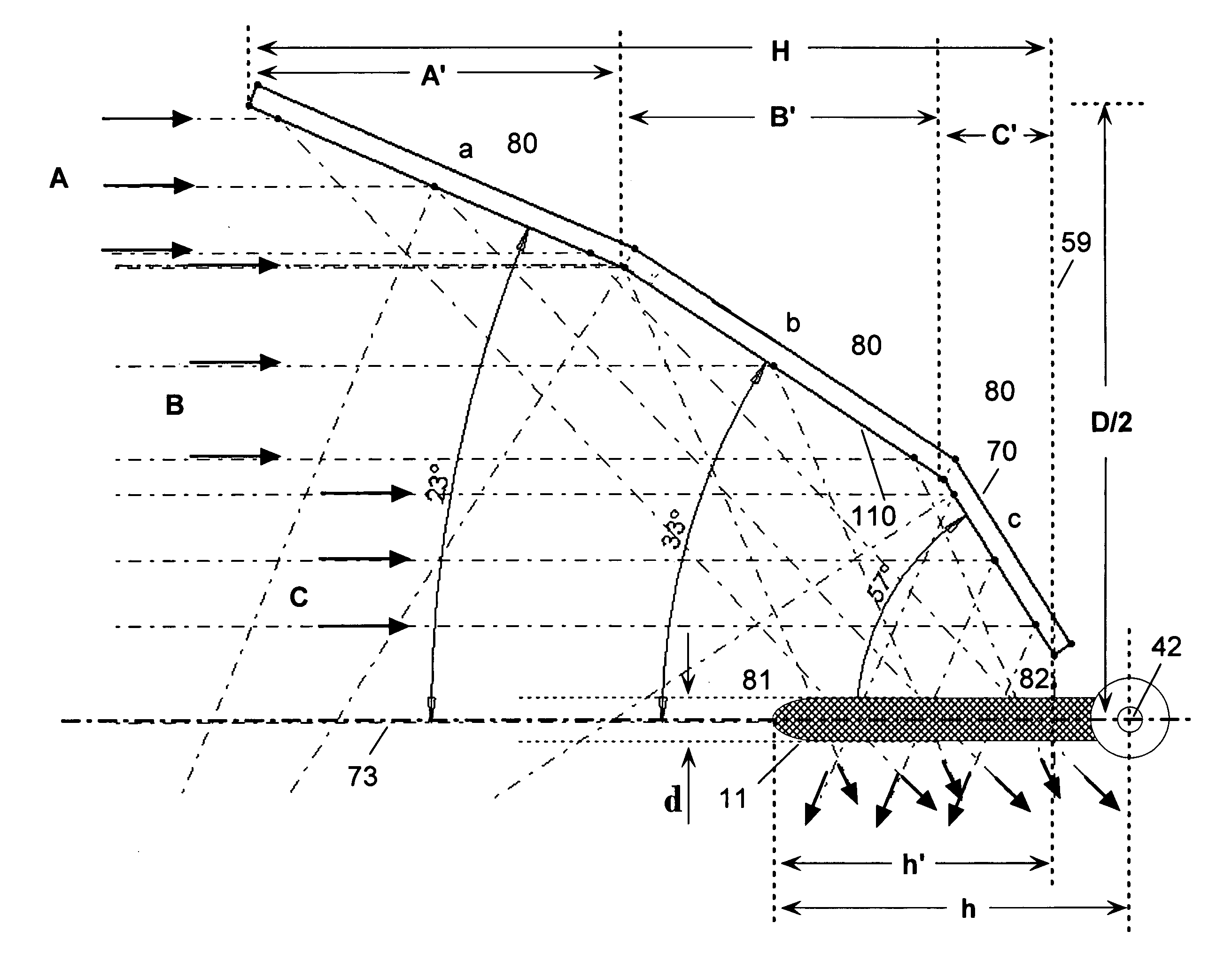
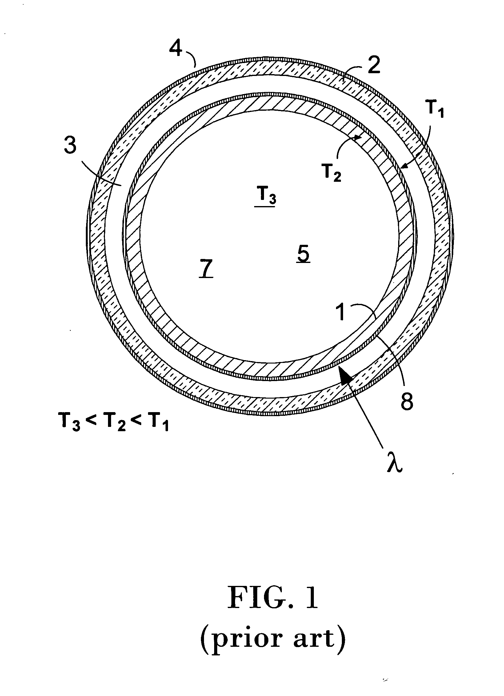
[0077]A receiver tube of the prior art, in FIG. 1, typically is provided with receiver tube (1) having low-emissivity outer coating (8), with such outer coating typically designed to simultaneously maximize absorption of solar wavelengths (typically 350-2000 nm, designated by lambda, λ). The receiver tube itself is typically a relatively high-temperature alloy, such as a stainless steel or other such metallic alloy. The receiver tube typically resides in a vacuum enclosure provided by an integral vacuum barrier tube (2) that is transmissive to the solar spectrum (e.g. borosilicate glass) and separated from the receiver tube by a vacuum space (3) providing thermal insulation. The vacuum barrier tube typically has an anti-reflective outer coating (4). The absorbing coating has many embodiments in the prior art, though cermets and other such composite coatings have become favored for intermediate-temperature applications, where receiver surfaces operate in the 300-1000 C range.

[0078]Be...


PUM


Abstract

The disclosed invention relates to solar-thermal receiver tubes for heating high-temperature fluids such as molten salts and oils, such as those used in conjunction with trough reflectors or concentric concentrators. The disclosed invention utilizes fused silica receiver tube assemblies that provide optical absorption by way of optically-absorbing media that is imbedded within the thermal transfer fluid, preferably comprising inorganic “dyes” that comprise pulverized thin film coatings or dissolved materials that are specifically designed for maximizing optical absorption. Alternatively, the chemistry of the transfer fluid can be modified to increase optical absorption, or the optically absorbing media may comprise fine powders with density preferably similar to the thermal transfer fluid, such as fine graphite powder; or, in another preferred embodiment, absorbing means within the heat transfer fluid comprise a solid absorbing element disposed along the central axis of the receiver tube's interior.

Description

TECHNICAL FIELD[0001]The present invention is related to and claims the benefit of U.S. provisional patent application 61 / 335,755 (Hilliard), filed Jan. 11, 2010, U.S. provisional patent application 61 / 337,338 (Hilliard), filed Feb. 1, 2010, and U.S. provisional patent application 61 / 396,387 (Hilliard), filed May 26, 2010, all of which applications are, in their entirety, incorporated herein by reference. The present invention relates in general to solar-thermal receiver tubes utilized for high-temperature applications, wherein heat energy is provided by an optical concentrator that concentrates solar energy onto a tubular absorber that results in heating of an oil or molten salt that is flowed through the receiver tube.BACKGROUND ART[0002]There exists a need in thermal-solar applications for maximizing efficiency with which collected solar radiation is converted into heat within the thermal transfer medium. Existing technologies that operate with high temperature fluids such as oil...

Claims


Application Information

Patent Timeline
IPC IPC(8): F24J2/05H01L31/052F24S10/30F24S10/40F24S10/70F24S20/20F24S23/74
CPCF24J2/055H01L31/0525F24S10/45F24S20/20F24S23/74H01L31/0547Y02E10/44Y02E10/52Y02E10/40
Inventor HILLIARD, DONALD BENNETT
Owner HILLIARD DONALD BENNETT
Why Eureka
Try Eureka