Spin-on-glass assisted polishing of rough substrates

a technology of surface roughness and spin-on-glass, which is applied in the direction of vacuum evaporation coating, ion implantation coating, coating, etc., can solve the problems of reducing the quality of polishing, different hardness of the different phases of steel, and limiting the surface roughness obtainable to about 5 nm

Inactive Publication Date: 2015-07-16
INMOLD BIOSYST
View PDF0 Cites 20 Cited by
  • Summary
  • Abstract
  • Description
  • Claims
  • Application Information

AI Technical Summary

Benefits of technology

[0006]It is an object of the present invention to present a technological solution, where a smooth film may be formed on a rough substrate, thus reducing polishing cost, increasing the surface anti-corrosion quality by reducing the number of defects and decreasing the surface roughness.
[0076]In some embodiments the reflow step comprises a thermal and solvent assisted process in a protected atmosphere to prevent reaction of the SOG with components of the atmosphere, in particular oxygen. The SOG film comprising adsorbed solvent is heated and surface tension makes the SOG reflow to minimize surface area, thus reducing the surface roughness.

Problems solved by technology

Steel surfaces may be polished, but there are several challenges in this process.
One is the purity of the steel that is very critical as even very small impurities will give rise to small holes or particle release during polishing, thus reducing the quality of the polishing.
Another limiting factor of this method is the different hardness of the different phases of the steel, limiting the surface roughness obtainable to about 5 nm, as the softer phase will be removed faster than the harder phase.
Furthermore steel is difficult to structure using conventional methods, as dry etching methods such as reactive ion etching is not possible, therefore only allowing for isotropic etching, greatly limiting obtainable micro and nano topographies.
Furthermore, steel may be corroded by contact with many different corrosive species, such as H2S or halogens.

Method used


Image

  • Spin-on-glass assisted polishing of rough substrates
  • Spin-on-glass assisted polishing of rough substrates
  • Spin-on-glass assisted polishing of rough substrates

Examples


Embodiment Construction

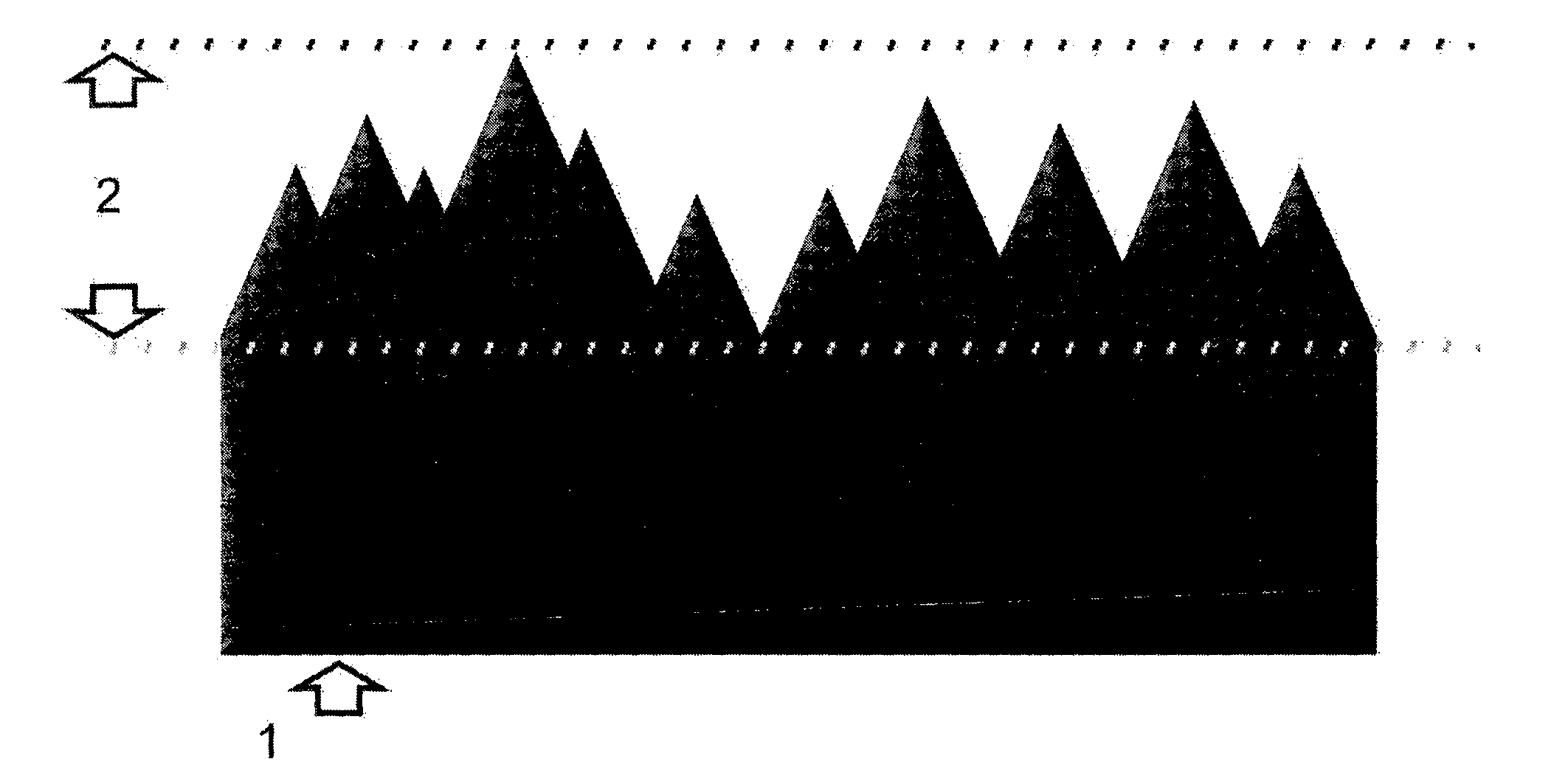
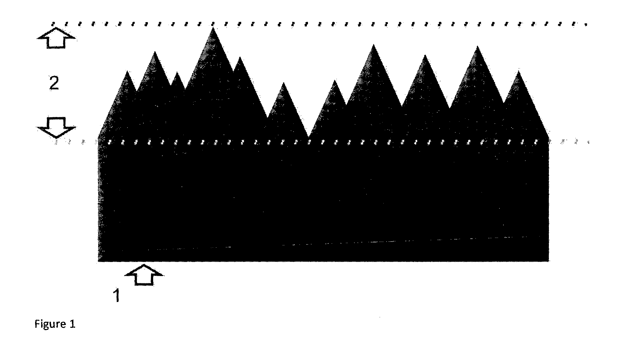
[0015]Conventional metallic or ceramic surfaces used in processing industry and other applications are often treated to decrease the surface roughness. This is often done to decrease friction of the surface, to increase reflectivity, or to improve other functional properties of the surface. The prevalent method to decrease the surface roughness is abrasive diamond polishing, where a paste of diamond powder dispersed in a liquid or a wax is rubbed onto the surface, thus decreasing the surface roughness. This method is relative expensive, especially on complex parts or large parts, where the polishing has to be performed manually. Alternatives such as electropolishing is also used, however only a limited number of materials are compatible with this process. It would therefore be advantageous if a process to reduce surface roughness where present, that had the following features: Material independent, applicable to complex and large geometries, cost effective and being fast with a high...


PUM

PropertyMeasurementUnit
temperatureaaaaaaaaaa
surface roughnessaaaaaaaaaa

Abstract

A method produces a smooth surface on a rough substrate. The rough substrate is coated with a film or particles of spin-on-glass (SOG) dissolved in a solvent using spin coating, spray coating or dip coating. The SOG is made to reflow by using thermal melting and solvent thinning. The reflow is done in an atmosphere containing a partial pressure of the solvent. The reflow allows the SOG to partially melt and to decrease the surface roughnesss of the film. The SOG is cured by thermal curing or UV exposure radiation curing into a hard durable and chemical inert silicon dioxide film. The SOG can be hydrogen silsesquioxane or methyl silsesquioxane dissolved in either methyl isobutyl ketone or volatile methyl siloxanes. The method can include embossing, chemical mechanical polishing, etching and functionalizing the surface. The substrate can be a cast, mould or form for producing a polymer or a glass replica.

Description

FIELD OF THE INVENTION[0001]The present invention relates to a method and apparatus for smoothening rough surfaces.BACKGROUND OF THE INVENTION[0002]In construction, mechanical and consumer applications, it is desirable to have a perfectly planar surface to defined areas of articles for use as low friction surfaces. A method of reducing surface roughness of such articles in a higher quality than by using state-of-the-art tools and methods is desirable, in particular if such reduction of the surface roughness of the said articles may be performed at a relative low cost. In particular articles made of hard metals or metal alloys, such as steel or aluminum, or ceramic materials such as wolfram carbide or titanium oxide, which are time consuming and expensive to polish would be advantageous to reduce the surface roughness of.[0003]Steel surfaces may be polished, but there are several challenges in this process. One is the purity of the steel that is very critical as even very small impur...

Claims


Application Information

Patent Timeline
Patent Type & Authority Applications(United States)
IPC IPC(8): C04B41/50C04B41/87C04B41/00B05D3/04B05D1/00
CPCC04B41/5035B05D3/0453C04B41/87C04B41/009B05D1/005B29C33/56
Inventor PRANOV, HENRIK
Owner INMOLD BIOSYST
Why Eureka
Try Eureka