Humic Acid-Derived Conductive Foams and Devices

Active Publication Date: 2018-03-01
GLOBAL GRAPHENE GRP INC
View PDF1 Cites 3 Cited by
  • Summary
  • Abstract
  • Description
  • Claims
  • Application Information

AI Technical Summary

Benefits of technology

[0061]In a preferred embodiment, the present invention provides a roll-to-roll process for producing a solid HA foam or HA-derived foam composed of multiple pores and pore walls The process comprises: (a) preparing a humic acid dispersion having multiple humic acid molecules or sheets dispersed in a liquid medium, wherein the humic acid is selected from oxidized humic acid, reduced humic acid, fluorinated humic acid, chlorinated humic acid, brominated humic acid, iodized humic acid, hydrogenated humic acid, nitrogenated humic acid, doped humic acid, chemically functionalized humic acid, or a combination thereof and wherein the dispersion contains an optional blowing agent having a blowing agent-to-humic acid weight ratio from 0/1.0 to 1.0/1.0; (b) continuously or intermittently dispensing and depositing the HA dispersion onto a surface of a supporting substrate to form a wet layer of HA material, wherein the supporting substrate is a continuous thin film supplied from a feeder roller and collected on a collector roller; (c) partially or completely removing the liquid medium from the wet layer of humic acid to form a dried layer of humic acid in a heating zone or multiple heating zones; and (d) heat treating the dried layer of humic acid in one of these heating zones containing a heating temperature from 80° C. to 500° C. at a desired heating rate sufficient to activate the blowing agent for producing the humic acid-derived foam having a density from 0.01 to 1.7 g/cm3 or a specific surface area from 50 to 3,000 m2/g. In this process, heat treatments occur in situ during the roll-to-roll procedure. This is a highly cost-effective process amenable to mass production of HA-derived graphitic foam sheets that are wrapped around on a roller for ease of shipping and handling

Problems solved by technology

However, CNTs are difficult to produce and are extremely expensive.
Further, CNTs are known to be difficult to disperse in a solvent or water and difficult to mix with other materials.
These characteristics have severely limited their scope of application.
There are several major problems associated with this conventional chemical production process:(1) The process requires the use of large quantities of several undesirable chemicals, such as sulfuric acid, nitric acid, and potassium permanganate or sodium chlorate.(2) The chemical treatment process requires a long intercalation and oxidation time, typically 5 hours to five days.(3) Strong acids consume a significant amount of graphite during this long intercalation or oxidation process by “eating their way into the graphite” (converting graphite into carbon dioxide, which is lost in the process).
It is not unusual to lose 20-50% by weight of the graphite material immersed in strong acids and oxidizers.(4) The thermal exfoliation requires a high temperature (typically 800-1,200° C.) and, hence, is a highly energy-intensive process.(5) Both heat- and solution-induced exfoliation approaches require a very tedious washing and purification step.
During the high-temperature exfoliation, the residual intercalate species retained by the flakes decompose to produce various species of sulfuric and nitrous compounds (e.g., NOx and SOx), which are undesirable.
The process must be carefully conducted in a vacuum or an extremely dry glove box environment since pure alkali metals, such as potassium and sodium, are extremely sensitive to moisture and pose an explosion danger.
This process is not amenable to the mass production of NGPs.
However, these processes are not suitable for mass production of isolated graphene sheets for composite materials and energy storage applications.
The Ni- or Cu-catalyzed CVD process does not lend itself to the deposition of more than 5 graphene planes (typically <2 nm) beyond which the underlying Ni or Cu layer can no longer provide any catalytic effect.
The CVD graphene films are extremely expensive.
This is a slow process that thus far has produced very small graphene sheets.
There are three major met

Method used


Image

  • Humic Acid-Derived Conductive Foams and Devices
  • Humic Acid-Derived Conductive Foams and Devices
  • Humic Acid-Derived Conductive Foams and Devices

Examples


example 1

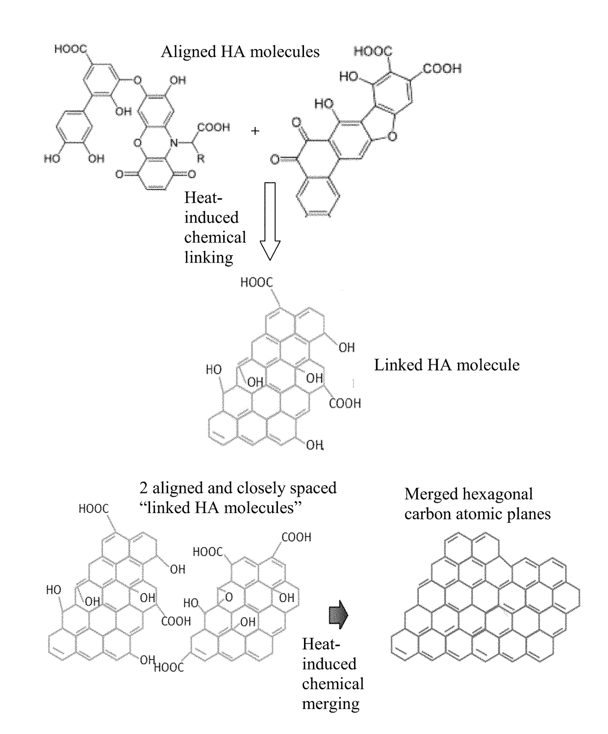
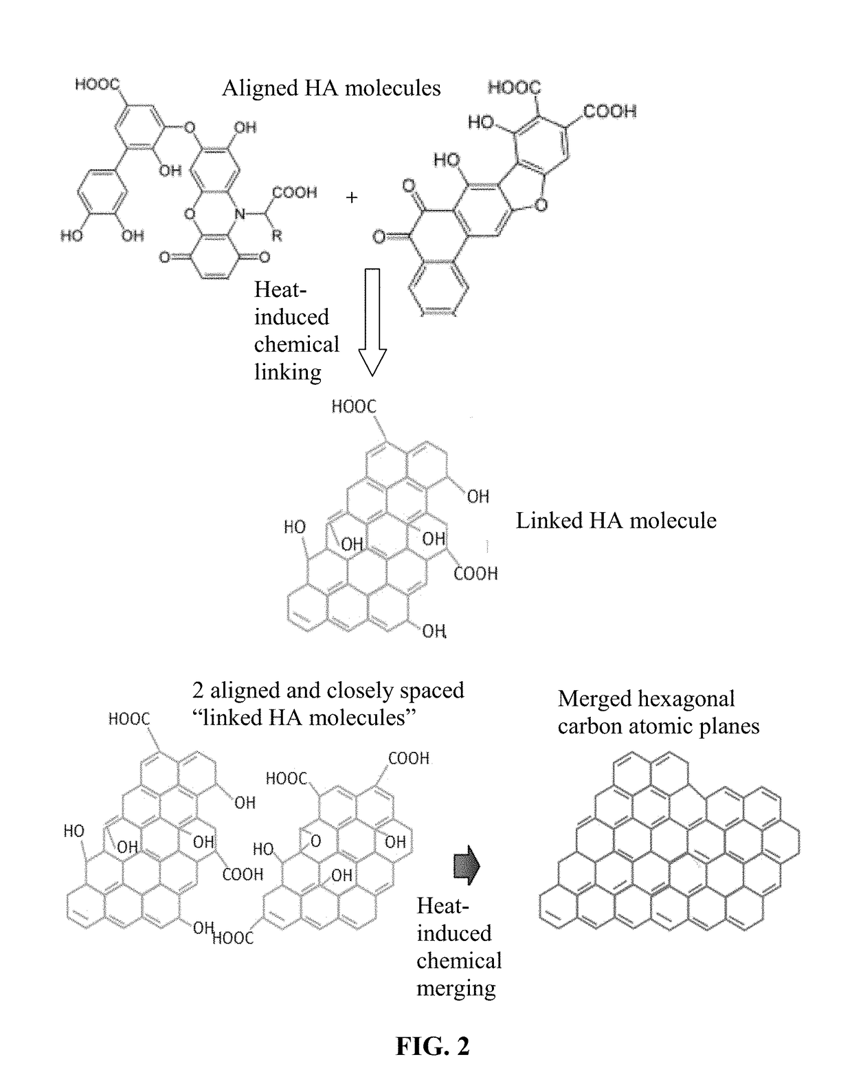
Humic Acid and Reduced Humic Acid From Leonardite

[0145]Humic acid can be extracted from leonardite by dispersing leonardite in a basic aqueous solution (pH of 10) with a very high yield (in the range of 75%). Subsequent acidification of the solution leads to precipitation of humic acid powder. In an experiment, 3 g of leonardite was dissolved by 300 ml of double deionized water containing 1M KOH (or NH4OH) solution under magnetic stirring. The pH value was adjusted to 10. The solution was then filtered to remove any big particles or any residual impurities. The resulting humic acid dispersion, containing HC alone or with the presence of a blowing agent, was cast onto a glass substrate to form a series of films for subsequent heat treatments.

[0146]In some samples, a chemical blowing agent (hydrazo dicarbonamide) was added to the suspension just prior to casting. The resulting suspension was then cast onto a glass surface using a doctor's blade to exert shear stresses, inducing HA mol...

example 2

Various Blowing Agents and Pore-Forming (Bubble-Producing) Processes

[0148]In the field of plastic processing, chemical blowing agents are mixed into the plastic pellets in the form of powder or pellets and dissolved at higher temperatures. Above a certain temperature specific for blowing agent dissolution, a gaseous reaction product (usually nitrogen or CO2) is generated, which acts as a blowing agent. However, a chemical blowing agent cannot be dissolved in a graphene material, which is a solid, not liquid. This presents a challenge to make use of a chemical blowing agent to generate pores or cells in a graphene material.

[0149]After extensive experimenting, we have discovered that practically any chemical blowing agent (e.g. in a powder or pellet form) can be used to create pores or bubbles in a dried layer of graphene when the first heat treatment temperature is sufficient to activate the blowing reaction. The chemical blowing agent (powder or pellets) may be dispersed in the liqu...

example 3

Preparation of Humic Acid From Coal

[0154]In a typical procedure, 300 mg of coal was suspended in concentrated sulfuric acid (60 ml) and nitric acid (20 ml), and followed by cup sonication for 2 h. The reaction was then stirred and heated in an oil bath at 100 or 120° C. for 24 h. The solution was cooled to room temperature and poured into a beaker containing 100 ml ice, followed by a step of adding NaOH (3M) until the pH value reached 7.

[0155]In one experiment, the neutral mixture was then filtered through a 0.45-mm polytetrafluoroethylene membrane and the filtrate was dialyzed in 1,000 Da dialysis bag for 5 days. For the larger humic acid sheets, the time can be shortened to 1 to 2 h using cross-flow ultrafiltration. After purification, the solution was concentrated using rotary evaporation to obtain solid humic acid sheets. These humic acid sheets alone and their mixtures with a blowing agent were re-dispersed in a solvent (ethylene glycol and alcohol, separately) to obtain severa...


PUM

PropertyMeasurementUnit
Fractionaaaaaaaaaa
Pore sizeaaaaaaaaaa
Pore sizeaaaaaaaaaa

Abstract

A humic acid-derived foam composed of multiple pores and pore walls, wherein the pore walls contain single-layer or few-layer humic acid-derived hexagonal carbon atomic planes or sheets, the few-layer hexagonal carbon atomic planes or sheets have 2-10 layers of stacked hexagonal carbon atomic planes having an inter-planar spacing d002 from 0.3354 nm to 0.40 nm as measured by X-ray diffraction, and the single-layer or few-layer hexagonal carbon atomic planes contain 0.01% to 25% by weight of non-carbon elements, and wherein the humic acid is selected from oxidized humic acid, reduced humic acid, fluorinated humic acid, chlorinated humic acid, brominated humic acid, iodized humic acid, hydrogenated humic acid, nitrogenated humic acid, doped humic acid, chemically functionalized humic acid, or a combination thereof.

Description

FIELD OF THE INVENTION[0001]The present invention relates generally to the field of carbon / graphite foams and, more particularly, to a new form of conductive foam derived from humic acid, devices containing such a humic acid-derived foam, and the process for producing same.BACKGROUND OF THE INVENTION[0002]Carbon is known to have five unique crystalline structures, including diamond, fullerene (0-D nano graphitic material), carbon nano-tube or carbon nano-fiber (1-D nano graphitic material), graphene (2-D nano graphitic material), and graphite (3-D graphitic material). Other than fullerene, all these materials can be made into a foamed structure.[0003]The carbon nano-tube (CNT) refers to a tubular structure grown with a single wall or multi-wall. Carbon nano-tubes (CNTs) and carbon nano-fibers (CNFs) have a diameter on the order of a few nanometers to a few hundred nanometers. Their longitudinal, hollow structures impart unique mechanical, electrical and chemical properties to the ma...

Claims


Application Information

Patent Timeline
IPC IPC(8): C02F1/28C09K3/32B01J20/24B01J20/28C09K5/14H01B1/12C08H7/00B01D17/02
CPCC02F1/286C09K3/32B01J20/24B01J20/28045B01J20/28011C02F2303/16C09K5/14H01B1/128C08H6/00B01D17/0202C02F2101/32B01J20/28083C02F1/40C02F2103/16
Inventor ZHAMU, ARUNAJANG, BOR Z.
Owner GLOBAL GRAPHENE GRP INC
Why Eureka
Try Eureka